Product Overview
The CP2102 USB to TTL UART Serial Converter Module is a compact, high-performance serial communication adapter that bridges the gap between a computer’s USB port and a microcontroller’s UART (Universal Asynchronous Receiver/Transmitter) interface. Based on the industry-leading CP2102 bridge controller from Silicon Labs, this module creates a virtual COM port on your computer, allowing you to program, debug, and communicate with embedded systems that lack native USB connectivity .
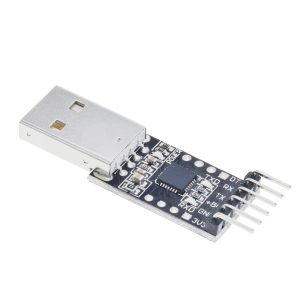
Whether you are working with an Arduino Pro Mini, ESP8266, ESP32, STM32, or other microcontrollers, this module provides a simple, reliable solution for serial communication . The board features a standard 6-pin interface with labels printed on the silk screen, plus dedicated 3.3V and 5V power output pins, and includes a self-recovery fuse for protection against accidental short circuits .
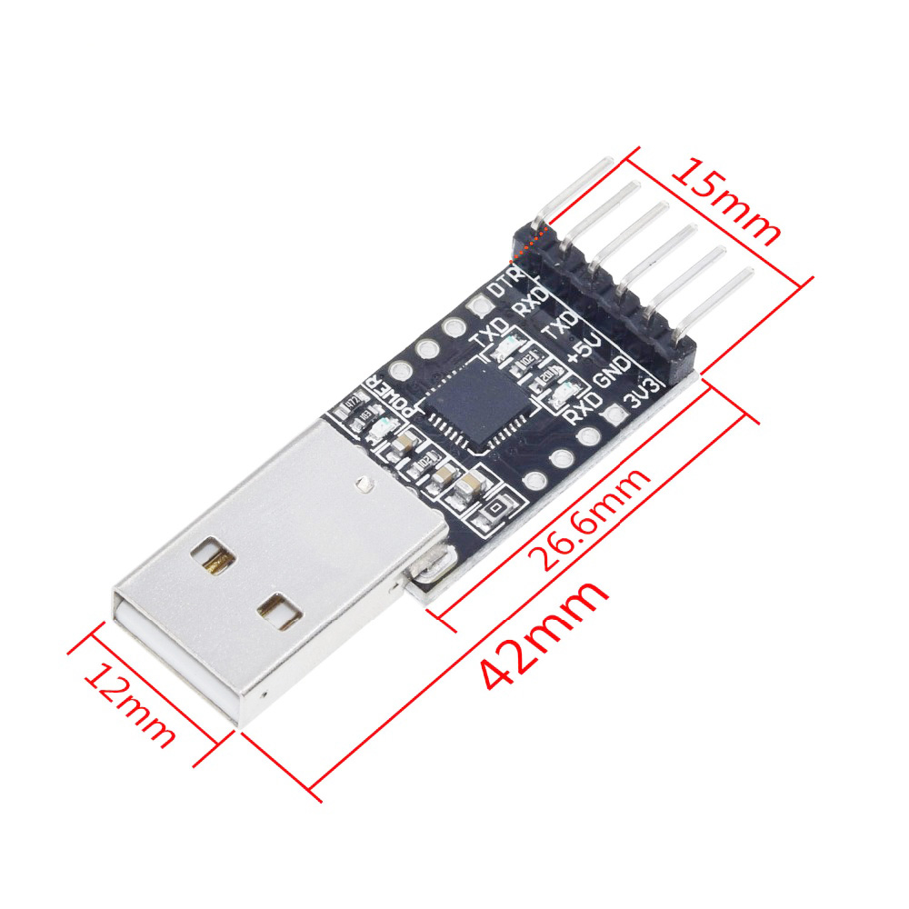
With a compact PCB size of just 26.5mm × 15.6mm and a full-speed USB 2.0 interface, this converter is perfect for programming, firmware updates, and serial debugging of a wide range of embedded systems . It’s a direct replacement for similar adapters like the FT232 and is widely recognized for its reliability and cross-platform compatibility .
Key Features
-
Genuine CP2102 Chipset: Based on the high-performance Silicon Labs CP2102 USB-to-UART bridge controller with full hardware handshaking support .
-
Broad Baud Rate Support: Supports baud rates from 300 bps up to 1 Mbps or even 921,600 bps, making it suitable for high-speed data transmission and programming .
-
6-Pin Layout with Auto-Reset: Standard 6-pin 2.54mm pitch pinout (DTR, RX, TX, VCC, 5V, GND) featuring a DTR line for automatic reset of Arduino-compatible boards during upload .
-
Dual Voltage Output: Provides both 3.3V and 5V power outputs to supply your target device. The 5V output is limited to 500mA (typical USB standard) .
-
Integrated Protection: Features a self-recovery fuse that protects your computer’s USB port and the target device in the event of an accidental short circuit .
-
Visual Status LEDs: Three onboard LEDs provide clear status indication: POWER (red), TXD (data transmission), and RXD (data reception) for real-time activity monitoring .
-
USB 2.0 Compliant: Meets USB 2.0 full-speed (12 Mbps) specifications, ensuring compatibility with modern computers and operating systems .
-
No External Crystal Required: The chip features an integrated clock, eliminating the need for external crystal oscillators and simplifying design and use .
-
Cross-Platform Driver Support: Works out of the box or with simple driver installation on Windows, macOS, and Linux, with Silicon Labs providing official drivers .
-
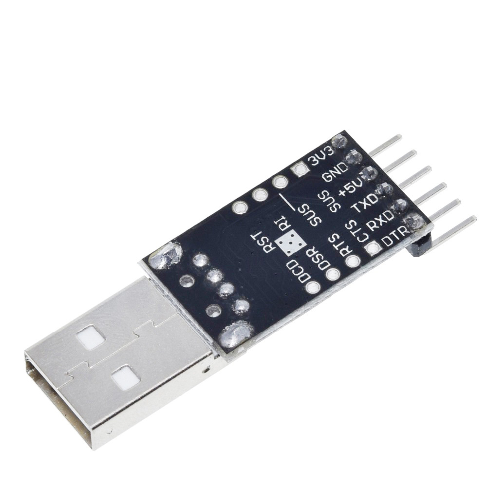
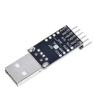
Extra I/O Pin Support: In addition to the main 6 pins, the RX, TX, RTS, and CTS pins are accessible on the side for advanced debugging and hardware handshaking .
Technical Specifications
Pinout & Interface Guide
The board is clearly labeled with the pin functions on the silk screen:
6-Pin Main Header (2.54mm Pitch)
-
3V3: 3.3V Power Output (regulated from USB)
-
5V: 5V Power Output (derived directly from USB VBUS)
-
TXD: Transmit Data (Connect to RX of your device)
-
RXD: Receive Data (Connect to TX of your device)
-
DTR: Data Terminal Ready (often used for auto-reset)
-
GND: Ground connection
Auxiliary Side Pins (Drilled Pads)
LED Indicators
-
PWR: Power indicator (illuminates when the module is connected to USB)
-
TXD: Data transmission indicator (blinks when sending data from PC to device)
-
RXD: Data reception indicator (blinks when receiving data from device to PC)
Usage Guide
Wiring Instructions
IMPORTANT: Always connect the ground (GND) between the CP2102 module and your target device first.
Standard Programming Connection (e.g., for Arduino Pro Mini or ESP32):
Wiring for Basic Serial Communication (No Auto-Reset):
Software Setup
1. Install Drivers
-
Windows: The drivers may install automatically. If not, download the “CP210x Universal Windows Driver” from the Silicon Labs website .
-
macOS: Drivers are usually included; restart your computer if the device is not recognized.
-
Linux: Drivers are built into the kernel (typically cdc-acm). The device will appear as /dev/ttyUSB0 or /dev/ttyACM0.
2. Identify the COM Port
-
Windows: Open Device Manager. Look for “Silicon Labs CP210x USB to UART Bridge” under Ports (COM & LPT) . Note the COM port number.
-
macOS/Linux: Open a terminal and type ls /dev/tty.*. Look for a device named tty.SLAB_USBtoUART or ttyUSB0.
3. Verify Communication
-
Open a serial terminal program (e.g., PuTTY, Arduino Serial Monitor, CuteCom).
-
Select the COM port and set the baud rate (e.g., 115200).
-
The terminal will display data sent from your microcontroller.
Application Examples
1. Programming an Arduino Pro Mini
Connect the module as shown in the wiring diagram. In the Arduino IDE, ensure the correct COM port and board (“Arduino Pro or Pro Mini”) are selected, then click Upload. The DTR line will handle the reset automatically.
2. Programming an ESP32 or ESP8266
For these 3.3V logic boards, use the 3V3 pin for power. Connect TX->RX, RX->TX, and GND->GND. Put the ESP board into upload mode manually (usually by holding BOOT and pressing EN) or use an auto-reset circuit .
3. Debugging / Logging Sensor Data
Connect the module’s RX/TX/GND to the debug UART of your system. Use a serial terminal to monitor printf statements or sensor logs in real-time.
4. Flashing Firmware to STM32 (“Blue Pill”)
Connect the CP2102 to the STM32’s UART1 pins (PA9/TX, PA10/RX). Set BOOT0 jumper to “1” and reset to enter bootloader mode, then use “STM32Flash” or a similar tool to upload the binary file
Q: What is the difference between the CP2102 and the CH340 or FT232RL?
The CP2102 is generally considered to have superior stability and more reliable drivers than the CH340, especially on macOS . It supports higher baud rates and more advanced features than the CH340. While the FT232RL is also excellent, the CP2102 is often more cost-effective while maintaining high reliability and cross-platform compatibility .
Q: Is this module compatible with a 5V microcontroller (like an Arduino Uno)?
Yes. The module has a native 5V output pin and its TXD/RXD logic levels are 5V tolerant when using the 5V power rail. You can connect it directly to the UART pins of a 5V Arduino, provided the connections are correct.
Q: Is it compatible with a 3.3V microcontroller (like an ESP32)?
Yes. The module also has a dedicated 3.3V output pin. For 3.3V logic devices, use the 3.3V pin for power and the module’s logic level will match
Q: What does the "DTR" pin do? Why is it important?
The DTR (Data Terminal Ready) pin is used to automatically reset a connected microcontroller board (like an Arduino) when a new sketch is uploaded. It pulls the reset line low, triggering the bootloader, so you don’t have to time the Reset button press manually
Q: What are the RTS and CTS pins for?
RTS (Request to Send) and CTS (Clear to Send) are used for hardware flow control. They are essential for high-speed communications or when connecting to devices with limited buffer space to prevent data loss. For most standard programming tasks (Arduino, ESP32), these pins are not necessary and can be left unconnected .
Q: My computer doesn't recognize the device. What should I do?
Follow this checklist :
-
Driver issue: Download and install the latest CP210x drivers directly from the Silicon Labs website.
-
USB Cable: Ensure you are using a data cable, not a charge-only cable.
-
Check Device Manager: On Windows, check under “Universal Serial Bus devices” for any unrecognized devices with a yellow warning icon.
Q: I can't upload code to my board. The upload gets stuck.
This is often a connection or auto-reset issue:
-
Verify wiring: Double-check that the TX pin on the CP2102 is connected to the RX pin on your target board, and RX is connected to TX.
-
Check DTR connection: For Arduino-compatible boards, ensure the DTR pin is correctly connected.
-
Manual Reset: If auto-reset fails, remove the DTR connection. Click “Upload” in the IDE and manually press the Reset button on your target board about 2 seconds after you see the “Compiling…” progress bar finish
Q: Is the module safe to connect to my computer's USB port?
Yes. The module features an onboard self-recovery fuse. In the event of an accidental short circuit on the target device, the fuse will trip to protect your computer’s USB port and the module itself. It will automatically reset once the short is removed
Q: Why are there three LEDs on the board?
– PWR (Red): Lights up when the board receives power from the USB port.
Q: What can I build with this CP2102 module?
Popular applications include :
-
Programming: Uploading code to Arduino Pro Mini, ESP32, ESP8266, and STM32 “Blue Pill”.
-
Debugging: Monitoring serial output (e.g., Serial.print) from any microcontroller .
-
PC Interface: Sending commands from a PC application (Python, C#, etc.) to control embedded hardware like relays or motors.
-
Data Logging: Receiving sensor data from a remote device for visualization on a PC.
Q: Can this module power my microcontroller project?
Yes, but with limits. The 5V output is derived directly from the USB port and is limited to the USB standard of 500mA. It is suitable for low-power microcontrollers (Arduino Pro Mini, ESP32 without Wi-Fi) but not for motors, servos, or high-power LED strips. For higher current requirements, use a separate external power supply.
Q: Are there any alternative chips to the CP2102?
Yes, common alternatives include the FTDI FT232R and the CH340/CH341 series. The CP2102 offers a good balance of cost, stability, and driver support