Product Overview
The CP2102 USB to TTL UART Serial Converter Module is a compact, high-performance serial communication adapter designed to bridge the gap between a computer’s USB port and a microcontroller’s UART interface. Based on the Silicon Labs CP2102 bridge controller, this module creates a virtual COM port on your computer, allowing you to program, debug, and communicate with embedded systems that lack native USB connectivity .
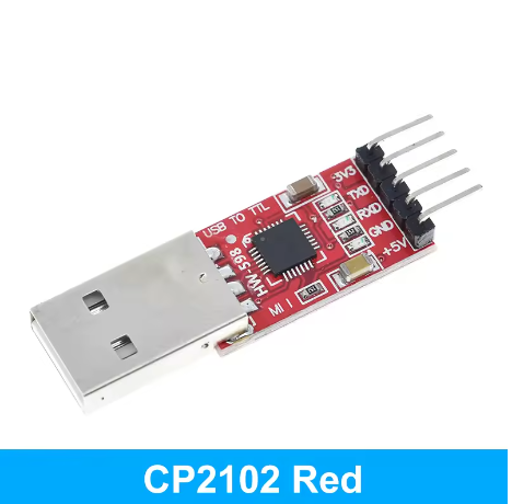
Featuring a 6-pin interface with clearly labeled silkscreen markings, this converter includes essential pins: 3.3V, 5V, TXD, RXD, DTR, and GND. The DTR (Data Terminal Ready) line supports auto-reset functionality, making it particularly convenient for programming Arduino Pro Mini, ESP8266, ESP32, and other development boards that require automatic reset during firmware upload .
Built with reliability in mind, the module incorporates an onboard self-recovery fuse that protects both your computer’s USB port and the connected target device in the event of an accidental short circuit or overcurrent condition. The TX and RX status LEDs provide real-time visual feedback of data transmission activity, simplifying debugging and troubleshooting.
With support for baud rates up to 1.5 Mbps and broad driver compatibility across Windows, macOS, and Linux, this CP2102-based converter is a trusted choice for electronics hobbyists, educators, and professionals working with microcontrollers and embedded systems .
Key Features
-
Genuine CP2102 Chipset: Based on the high-performance Silicon Labs CP2102 USB 2.0 to UART bridge controller, known for excellent stability and broad compatibility
-
6-Pin Interface with Auto-Reset: Standard 6-pin 2.54mm pitch pinout (3V3, 5V, TXD, RXD, DTR, GND) featuring DTR line for automatic reset of Arduino-compatible boards during upload
-
Dual Voltage Output: Provides both 3.3V (up to 50mA) and 5V (up to 500mA) power outputs to supply your target device
-
Integrated Self-Recovery Fuse: Onboard resettable fuse protects your computer’s USB port and the module from short circuits and overcurrent conditions
-
High-Speed Communication: Supports baud rates from 300 bps up to 1.5 Mbps, suitable for high-speed data transmission and programming
-
Visual Status LEDs: Three onboard LEDs provide clear status indication: POWER (red), TXD (green), and RXD (blue/red) for real-time activity monitoring
-
USB 2.0 Compliant: Meets USB 2.0 full-speed (12 Mbps) specifications, ensuring compatibility with modern computers
-
Broad Driver Support: Works with official Silicon Labs VCP drivers on Windows, macOS, and Linux – plug-and-play on most modern systems
-
Compact Size: Small PCB footprint (approx. 42mm × 15mm) allows easy integration into projects and enclosures
Technical Specifications
Pinout & Interface Guide
The board features a 6-pin header (2.54mm pitch) with clearly labeled silkscreen markings:
Important Note: TXD and RXD are labeled from the CP2102’s perspective:
LED Indicators
Usage Guide
Wiring Instructions
IMPORTANT: Always connect the ground (GND) between the CP2102 module and your target device first.
Standard Programming Connection (e.g., for Arduino Pro Mini, ESP32, ESP8266)
Basic Serial Communication (No Auto-Reset)
Software Setup
1. Install Drivers
The CP2102 requires Virtual COM Port (VCP) drivers:
-
Windows: Download the “CP210x Universal Windows Driver” from Silicon Labs website. The driver may install automatically on Windows 10/11 .
-
macOS: Drivers are usually included; restart your computer if the device is not recognized .
-
Linux: Drivers are built into the kernel (cdc-acm). The device will appear as /dev/ttyUSB0 or /dev/ttyACM0 .
2. Identify the COM Port
-
Windows: Open Device Manager. Look for “Silicon Labs CP210x USB to UART Bridge” under Ports (COM & LPT) . Note the COM port number.
-
macOS/Linux: Open a terminal and type ls /dev/tty.*. Look for a device named tty.SLAB_USBtoUART or ttyUSB0.
3. Changing the COM Port Number (Windows)
If needed, you can change the COM port assignment:
-
Right-click the device in Device Manager → Properties
-
Select Port Settings tab → Click Advanced
-
Select a new COM port number from the dropdown menu
4. Verify Communication
-
Open a serial terminal program (e.g., PuTTY, Arduino Serial Monitor, CoolTerm)
-
Select the COM port and set the baud rate (e.g., 115200)
-
The terminal will display data sent from your microcontroller.
Application Examples
1. Programming an Arduino Pro Mini
Connect the module as shown in the wiring diagram above. In the Arduino IDE, select the correct COM port and board (“Arduino Pro or Pro Mini”), then click Upload. The DTR line will handle the reset automatically .
2. Programming an ESP32 or ESP8266
For these 3.3V logic boards, use the 3V3 pin for power. Connect TX→RX, RX→TX, and GND→GND. You may need to put the ESP board into upload mode manually (hold BOOT, press EN) .
3. Debugging / Logging Sensor Data
Connect the module’s RX/TX/GND to the debug UART of your system. Use a serial terminal to monitor Serial.print statements or sensor logs in real-time.
4. Flashing STM32 (“Blue Pill”)
Connect the CP2102 to the STM32’s UART1 pins (PA9/TX, PA10/RX). Set BOOT0 jumper to “1” and reset to enter bootloader mode, then use STM32CubeProgrammer or a similar tool to upload firmware .
Q: What is the difference between CP2102 and CH340 or FT232RL?
The CP2102 is widely considered to have superior stability and more reliable drivers than the CH340, especially on macOS . It supports higher baud rates and is generally more robust. While the FT232RL is also excellent, the CP2102 is often more cost-effective while maintaining high reliability and cross-platform compatibility
Q: Is this module compatible with 5V microcontrollers (like Arduino Uno)?
Yes. The module has a dedicated 5V output pin, and its TXD/RXD logic levels are 5V tolerant when using the 5V power rail. You can connect it directly to the UART pins of a 5V Arduino
Q: Is it compatible with 3.3V microcontrollers (like ESP32)?
Yes. The module also has a dedicated 3.3V output pin. For 3.3V logic devices, use the 3.3V pin for power, and the module’s logic level will match
Q: What does the DTR pin do? Why is it important?
The DTR (Data Terminal Ready) pin is used to automatically reset an Arduino-compatible board when uploading a new sketch. It pulls the reset line low, triggering the bootloader, so you don’t need to time the Reset button press manually
Q: Can I use this to connect a Raspberry Pi to a microcontroller?
Yes. The CP2102 can connect a Raspberry Pi (USB host) to a microcontroller’s UART. However, for direct GPIO serial on Raspberry Pi, you may prefer using the built-in UART pins with a level shifter.
Q: My computer doesn't recognize the device. What should I do?
Follow this checklist:
-
Driver issue: Download and install the latest CP210x drivers directly from the Silicon Labs website .
-
USB Cable: Ensure you are using a data cable, not a charge-only cable.
-
Check Device Manager: On Windows, check under “Universal Serial Bus devices” for any unrecognized devices with a yellow warning icon .
Q: I can't upload code to my board. The upload gets stuck.
This is often a connection or auto-reset issue:
-
Verify wiring: Double-check that TXD connects to RX on your target, and RXD connects to TX .
-
Check DTR connection: For Arduino-compatible boards, ensure the DTR pin is correctly connected to the board’s reset pin.
-
Manual Reset: If auto-reset fails, remove the DTR connection. Click “Upload” and manually press the Reset button on your target board about 2 seconds after compilation finishes.
Q: Is the module safe to connect to my computer's USB port?
Yes. The module features an onboard self-recovery fuse. In the event of an accidental short circuit on the target device, the fuse trips to protect your computer’s USB port and the module. It automatically resets once the short is removed .
Q: Why are there multiple LEDs on the board?
– PWR (Red): Lights up when the board receives power from the USB port .
Q: Can this module power my microcontroller project?
Yes, but with limits. The 5V output is derived directly from the USB port and is typically limited to 500mA (USB 2.0 standard). The 3.3V output is limited to about 50mA . It is suitable for low-power microcontrollers (Arduino Pro Mini, ESP32 without Wi-Fi) but not for motors, servos, or high-power LED strips. For higher current, use a separate external power supply.
Q: What is the maximum baud rate supported?
The CP2102 supports baud rates up to 1.5 Mbps, making it suitable for high-speed applications and fast firmware uploads .
Q: Can I use hardware flow control (RTS/CTS)?
This 6-pin version does not break out RTS/CTS pins. For hardware flow control applications, consider a version with full pin breakout or use software flow control (XON/XOFF).
Q: What can I build with this CP2102 module?
Popular applications include :
-
Programming: Upload code to Arduino Pro Mini, ESP32, ESP8266, STM32 “Blue Pill”
-
Debugging: Monitor serial output (Serial.print) from any microcontroller
-
PC Interface: Send commands from Python, C#, or other applications to control hardware
-
Data Logging: Receive sensor data from remote devices for PC visualization
-
GPS Module Interface: Connect GPS modules to computers for navigation software
-
Legacy Device Communication: Interface older serial devices with modern computers
Q: Can I use this with STM32 "Blue Pill" boards?
Yes. Connect the CP2102’s TX/RX to the STM32’s UART pins (PA9/PA10). Set BOOT0 to 1 and reset to enter bootloader mode for firmware upload
Q: What is the difference between a USB-to-TTL converter and a USB-to-RS232 converter?
A USB-to-TTL converter outputs 3.3V/5V logic levels suitable for directly connecting to microcontrollers. A USB-to-RS232 converter outputs ±12V signals for legacy serial ports. This CP2102 module is a TTL converter – do not connect it directly to RS232 devices .