DIY KIT 16 Channel 12-bit PWM/Servo Driver-I2C interface-PCA9685 for arduino or Raspberry pi shield module servo shield

SKU: FA2004 Tag:
Weight 0.020 kg
Dimensions 6.2 × 2.5 cm
Feature 1

Software reset feature (SWRST Call) allows the device via I2C bus reset

Feature 2

25MHz internal oscillator requires no external components

Feature 3

The maximum allowable 50MHz external clock input

Feature 4

Internal power-on reset

Feature 5

In the SDA / SCL inputs with noise filter

Feature 6

Output pin has edge generation rate control

Feature 7

No glitches on power-up (glitch) output

Feature 8

Hot-Access

Feature 9

Low standby current

Feature 10

Operating voltage range: 2.3V to 5.5V

Feature 11

5.5V tolerant inputs

Feature 12

Can operate at minus 40 degrees Celsius to 85 degrees Celsius environment

Feature 13

ESD protection exceeds 2000V HBM / JESD22-A114,200V MM / JESD22-A115 and 1000V CDM / JESD22-C101

Feature 14

JEDEC standard JESD78 lockout exceed 100mA test

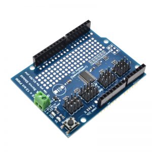
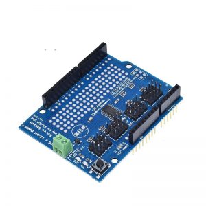
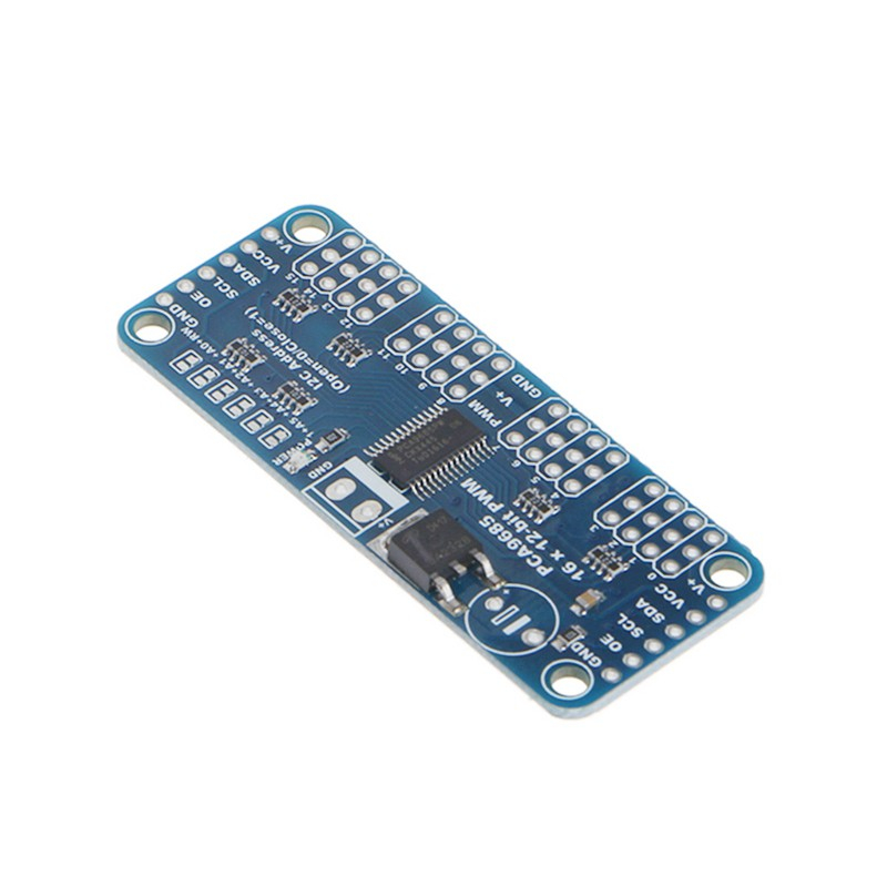
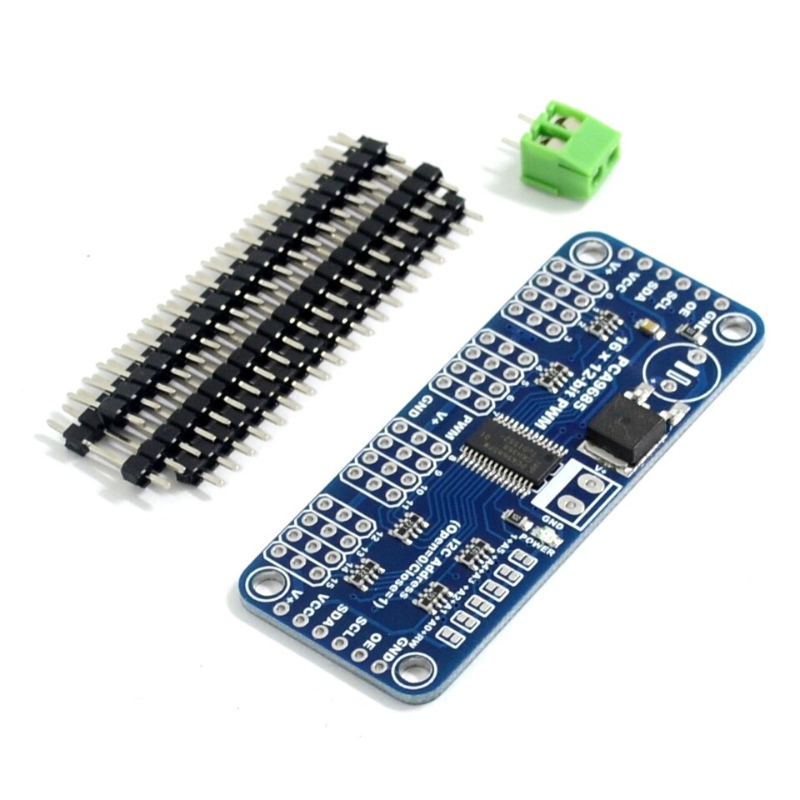
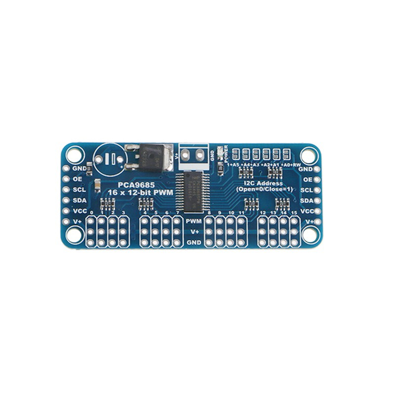
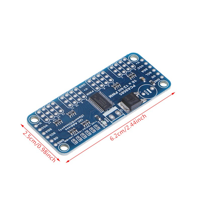
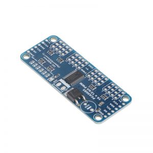
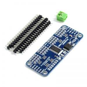
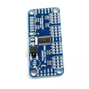
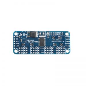
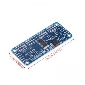
DIY KIT 16 Channel 12-bit PWM/Servo Driver-I2C interface-PCA9685  or Raspberry pi shield module servo shield

6 LED drivers, each output can be programmed to:

Turn off

Open

Programmable LED brightness

Programmable fuzzy group (dim) / Flashing LED brightness independent mixed with 1MHz Fast-mode Plus is compatible with high drive capability has 30mA on SDA I2C bus interface to drive highly capacitive bus.Each LED output can be achieved from the fully closed (the default) to 4096 (12) between the maximum brightness linear programmable brightness.

Software programmable open-drain LED output selection (the default is a push-pull) of 16 push-pull outputs (at 5V 25mA sink can absorb and provide 10mA current draw), no input function

Programmable output state is in response to an order to change or stop to achieve simultaneously update all outputs or by-byte (byte-by-byte) update output (default is “Stop command to change”)

Effective low output enable input pin when the pin is high, the LED output can be programmed to 0,1 or tri-state (high impedance power-on default)

6 hardware address pins so that the same can be connected to 62 PCA9685 I2C devices on the bus

LED output frequency (all LED) is typically 40Hz to 1000Hz (When the oscillator is 25MHz, the prescaler register default value 1EH 200Hz refresh rate will generate a)

4 software programmable I2C bus address (an LED group call (Call) address and three sub-LED call (Call) address) such that the device can be set in any combination to be addressed at the same time (e.g., a register used for ” All calls (All Call) “then all PCA9634 devices on the I2C bus can be addressed at the same time, while the second register for three different addresses, then a device group 1/3 bus devices can be addressed at the same time), you can enable and disable the software I2C bus address


Features

Software reset feature (SWRST Call) allows the device via I2C bus reset

25MHz internal oscillator requires no external components

The maximum allowable 50MHz external clock input

Internal power-on reset

In the SDA / SCL inputs with noise filter

Output pin has edge generation rate control

No glitches on power-up (glitch) output

Hot-Access

Low standby current

Operating voltage range: 2.3V to 5.5V

5.5V tolerant inputs

Can operate at minus 40 degrees Celsius to 85 degrees Celsius environment

ESD protection exceeds 2000V HBM / JESD22-A114,200V MM / JESD22-A115 and 1000V CDM / JESD22-C101

JEDEC standard JESD78 lockout exceed 100mA test

Package: TSSOP28 and HVQFN28


Hot Tags: DIY KIT 16 Channel 12-bit PWM/Servo Driver-I2C Interface-PCA9685 Or Raspberry PI Shield Module Servo Shield

Programmable fuzzy group (dim) / Flashing LED brightness independent mixed with 1MHz Fast-mode Plus is compatible with high drive capability has 30mA on SDA I2C bus interface to drive highly capacitive bus.Each LED output can be achieved from the fully closed (the default) to 4096 (12) between the maximum brightness linear programmable brightness.

Software programmable open-drain LED output selection (the default is a push-pull) of 16 push-pull outputs (at 5V 25mA sink can absorb and provide 10mA current draw), no input function

Programmable output state is in response to an order to change or stop to achieve simultaneously update all outputs or by-byte (byte-by-byte) update output (default is “Stop command to change”)

Effective low output enable input pin when the pin is high, the LED output can be programmed to 0,1 or tri-state (high impedance power-on default)

6 hardware address pins so that the same can be connected to 62 PCA9685 I2C devices on the bus

LED output frequency (all LED) is typically 40Hz to 1000Hz (When the oscillator is 25MHz, the prescaler register default value 1EH 200Hz refresh rate will generate a)

4 software programmable I2C bus address (an LED group call (Call) address and three sub-LED call (Call) address) such that the device can be set in any combination to be addressed at the same time (e.g., a register used for ” All calls (All Call) “then all PCA9634 devices on the I2C bus can be addressed at the same time, while the second register for three different addresses, then a device group 1/3 bus devices can be addressed at the same time), you can enable and disable the software I2C bus address

You may also like…