Dual-Channel LM393 Voltage Comparator Module – DC 12V 10A Max, Onboard IC for Precision Monitoring

SKU: FA2178-1
Comparator IC

LM393 (Texas Instruments) – Dual Differential Comparator

Supply Current

< 2mA at 12V (typical, excluding output loads)

Input Voltage Range

0V to VCC-1.5V (max approx. 10.5V with 12V supply)

Output Type

Open-Collector (requires external pull-up for logic-level use)

Output Sink Current (direct)

6mA typical (from IC); 10A Max with external driver (relay/MOSFET)

Response Time

1.3µs typical

Input Bias Current

25nA typical

Input Offset Voltage

2mV typical

Description

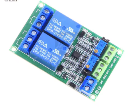
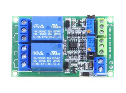
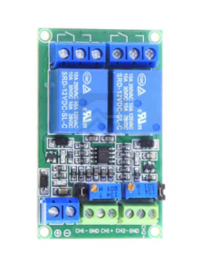
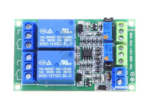
The Dual-Channel LM393 Voltage Comparator Module is a robust, high-performance analog signal processing board designed for precision voltage monitoring and threshold detection in 12V DC systems. At its heart lies the industry-standard LM393 dual differential comparator IC from Texas Instruments, a reliable component widely used in automotive, industrial, and battery management applications.

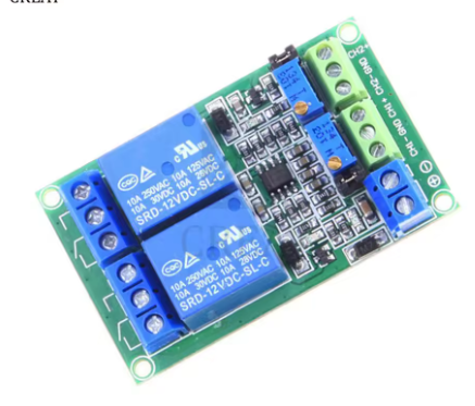
This module integrates two independent voltage comparators on a single board, each capable of comparing two analog input voltages and outputting a digital signal indicating which input is higher. When the voltage at the non-inverting input (+) exceeds the voltage at the inverting input (-), the corresponding open-collector output turns on (pulls low). Conversely, when the inverting input is higher, the output turns off (high impedance).

The 12V DC version of this module is specifically designed for automotive and industrial environments where 12V power is standard. The LM393 IC features a wide supply voltage range of 2V to 36V, making it perfectly suited for direct connection to 12V vehicle electrical systems (including the typical 13.8V to 14.4V alternator charging voltage). The module includes two precision potentiometers that allow users to set adjustable reference voltages for each comparator channel independently, enabling flexible threshold configuration without external components.

The module also features two onboard indicator LEDs that provide real-time visual feedback of each comparator’s output status. When an output is active (pulled low), the corresponding LED illuminates, allowing for immediate visual verification – particularly useful when troubleshooting 12V automotive circuits.

The LM393’s outputs are open-collector, meaning they can drive loads up to 10A when used with appropriate external transistors, MOSFETs, or relays. This makes the module ideal for directly controlling 12V automotive relays, warning lights, buzzers, and other actuators. The outputs are compatible with TTL, MOS, and CMOS logic levels and can be connected together to create wired-AND relationships.

Whether you are building a 12V battery low-voltage cutoff for lead-acid or LiFePO4 batteries, an automotive over-voltage protection system, a temperature-triggered fan controller, or a light-sensitive headlight switch, this LM393 dual comparator module delivers precise, reliable threshold detection in an easy-to-use 12V-compatible format.

Key Features

  • 12V DC Optimized Design – Specifically configured for automotive and industrial 12V systems (includes 12V relay drive capability)

  • Dual Independent Comparators – Two separate comparator channels on a single board for simultaneous monitoring of two different signals

  • LM393 Comparator IC – Industry-standard dual differential comparator with 2V–36V supply range; direct 12V compatibility

  • Wide Supply Voltage Range – Operates from 2V to 36V DC; perfect for 12V automotive (13.8V-14.4V alternator systems)

  • Adjustable Reference Voltage – Two precision potentiometers for setting independent threshold voltages from 0V to 12V on each channel

  • Onboard Status LEDs – Visual output indicators for each comparator channel; LED illuminates when output is active (low)

  • 10A Output Drive Capability – Open-collector outputs can control external relays, solenoids, or MOSFETs up to 10A (requires external driver stage)

  • Fast Response Time – 1.3µs typical propagation delay for rapid threshold detection in automotive safety applications

  • Input Common-Mode Range Includes Ground – Allows direct measurement of signals near 0V (e.g., current shunt monitoring)

  • Low Power Consumption – Approximately 1mA-2mA supply current at 12V, minimal load on vehicle electrical system

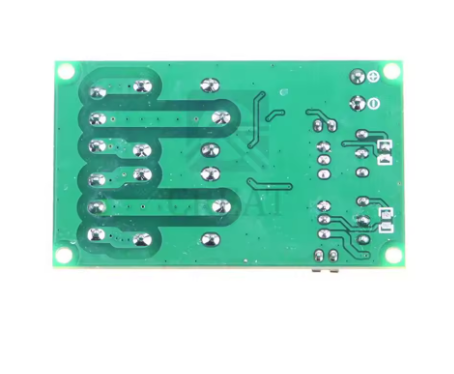
  • Compact Module Design – Small footprint with clearly labeled screw terminals for reliable 12V wiring

Technical Specifications 

Specification Value
Comparator IC LM393 (Texas Instruments) – Dual Differential Comparator
Recommended Supply Voltage 12V DC (automotive: 11V – 15V; IC supports 2V – 36V)
Supply Current < 2mA at 12V (typical, excluding output loads)
Input Voltage Range 0V to VCC-1.5V (max approx. 10.5V with 12V supply)
Output Type Open-Collector (requires external pull-up for logic-level use)
Output Sink Current (direct) 6mA typical (from IC); 10A Max with external driver (relay/MOSFET)
Response Time 1.3µs typical
Input Bias Current 25nA typical
Input Offset Voltage 2mV typical
Operating Temperature 0°C to 70°C (commercial grade; -40°C to 125°C versions available)
Board Dimensions Approx. 40mm × 27mm (varies by manufacturer)
Mounting 4× 3mm mounting holes
Terminal Type Screw terminals for reliable 12V wiring

Typical Usage

  • 12V Battery Low-Voltage Cutoff – Protect lead-acid, AGM, or LiFePO4 batteries from over-discharge; disconnect load when voltage drops below 10.5V-12.0V (configurable)

  • Automotive Over-Voltage Protection – Monitor alternator output; trigger warning light or disconnect sensitive electronics if voltage exceeds safe limit (15.5V typical)

  • Temperature-Controlled 12V Fans – Use with thermistor or temperature sensor to activate cooling fans when engine bay or equipment temperature exceeds set point

  • Light-Activated Headlight Switch – Connect photoresistor (LDR) to one input; automatically turn on 12V lights at dusk, off at dawn

  • Motor Over-Current Protection – Monitor current sense resistor voltage (e.g., using shunt); trigger relay shutdown when current exceeds 10A threshold

  • 12V Relay Control – Directly drive automotive relays (via transistor/MOSFET) for high-current load switching

  • Battery Charge Controller – Monitor battery voltage; start charging when voltage drops to set low threshold, stop when fully charged

  • Solar Charge Controller – Disconnect load when battery voltage is low; reconnect when battery recovers (requires hysteresis)

  • Window Comparator for Battery Health – Use both channels to detect battery in “normal zone” (e.g., 12.0V to 14.4V); illuminate status LED

  • Capacitive Fuel/Tank Level Sensing – Detect liquid level changes by comparing capacitive sensor output against reference

Q: What does "DC 12V 10A Max" mean on this module?

The LM393 IC itself cannot directly switch 10A. The “12V” refers to the recommended operating voltage (automotive 12V systems). The “10A Max” refers to the maximum load current that can be controlled when the comparator output is used to drive an external power transistor, MOSFET, or automotive relay rated for 12V/10A. For direct control of LEDs or low-power indicators (under 20mA), no external driver is needed.

Q: Can this module be used directly with a car's 12V electrical system?

Yes. The LM393 operates from 2V to 36V, making it fully compatible with automotive 12V systems, including the typical alternator charging voltage of 13.8V to 14.4V . However, the common-mode input range is VCC-1.5V, so with a 14.4V supply, inputs should be kept below approximately 12.9V. Use voltage dividers if measuring voltages near the supply rail.

Q: What is the difference between the 5V version and the 12V version?

The IC itself is the same LM393. The difference is in the configuration: the 12V version is optimized for 12V operation with appropriate reference voltage ranges (0-12V), relay drive capability for 12V loads, and screw terminals suited for automotive wiring. The 5V version is designed for 5V microcontroller systems. Both can be powered from 5V-12V, but the potentiometer reference range matches the supply voltage.

Q: How do I use this module to create a battery low-voltage cutoff for a 12V battery?
  1. Power the module from the 12V battery (VCC to battery positive, GND to negative)

  2. Use a voltage divider to scale battery voltage down to the comparator’s input range (e.g., 10kΩ+10kΩ divider reduces 15V to 7.5V)

  3. Connect the divided battery voltage to IN+

  4. Adjust the potentiometer on IN- to set your desired cutoff threshold (e.g., 10.5V for lead-acid)

  5. Connect comparator output to a relay driver (transistor + relay) that controls the load

  6. When battery voltage drops below threshold, comparator triggers relay to disconnect load

Q: Why is my output LED not lighting up?

The LED indicates when the comparator output is active (low). Check the following:

  • Ensure the module is properly powered (11V-15V DC)

  • Verify that the input voltage difference is correct (when (+) > (-), output is low)

  • Check that the onboard potentiometer is properly adjusted to set the reference voltage

  • If using open-collector output with external pull-up, ensure pull-up resistor is connected (to VCC)

  • For automotive installations, verify ground connections are clean and secure

Q: What is the input voltage range for this comparator at 12V?

The LM393’s common-mode input voltage range is 0V to VCC-1.5V . With a 12V supply (or 14.4V in a running vehicle), inputs must be between 0V and approximately 10.5V (12V supply) or 12.9V (14.4V supply). For monitoring 12V battery voltage directly (which can reach 14.4V), use a voltage divider (e.g., two 10kΩ resistors) to scale the voltage down by half before feeding to the comparator.

Q: Can I use this module to control a 12V automotive relay directly?

The LM393 output can sink only about 6mA-16mA directly, which is insufficient to energize most automotive relays (typically require 50mA-200mA coil current). You must use an external driver stage: either a transistor (e.g., 2N2222, BC548) or a logic-level MOSFET (e.g., IRLZ44N) between the comparator output and the relay coil. The “10A Max” rating refers to the load capacity of that external driver, not the comparator IC itself.

Q: How do I set the threshold voltage using the potentiometer?

The potentiometer creates a voltage divider between VCC and GND. The reference voltage is applied to one comparator input (typically the inverting input). With the module powered at 12V, the potentiometer adjusts the reference voltage from 0V to approximately 12V. Use a multimeter to measure the reference voltage at the test point while adjusting. Turn clockwise to increase reference voltage, counterclockwise to decrease.

Q: Why is my comparator oscillating or chattering near the threshold?

When the input voltage is very close to the reference voltage, noise can cause the output to oscillate. This is common in automotive environments with electrical noise from alternators, ignition systems, and motors. To prevent this, add positive feedback (hysteresis) by connecting a resistor (typically 100kΩ to 1MΩ) from the output to the non-inverting input. This creates a small voltage window (e.g., 0.2V-0.5V) around the threshold, preventing oscillations. Alternatively, use a comparator with built-in hysteresis (e.g., LM311 with appropriate configuration).