Product Overview
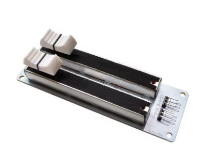
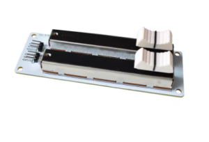
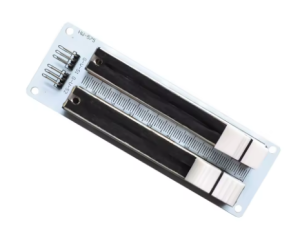
The Dual-Gang Slide Potentiometer Kit is a high-quality, dual-channel analog input component designed for DIY electronics projects, audio mixing equipment, and microcontroller-based control interfaces. Featuring a B10K (10k ohm) linear taper resistance element, this slide potentiometer provides smooth, precise, and proportional control across its entire travel length .
The “dual-gang” configuration means this component contains two independent potentiometers operated by a single sliding mechanism . This design is essential for stereo audio applications where both left and right channels must be adjusted simultaneously with perfect tracking. Each channel provides its own analog output, allowing you to read two independent voltage signals from a single slider.
This slide potentiometer is ideal for applications requiring linear motion control such as audio mixing consoles, lighting desks, DJ equipment, test instruments, and DIY electronic control panels. Unlike rotary potentiometers, the linear sliding action offers a visual indication of the current setting, making it particularly useful where at-a-glance status is valuable.
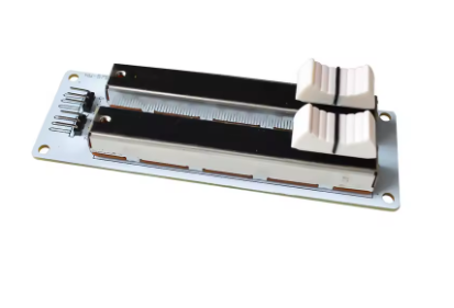
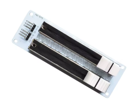
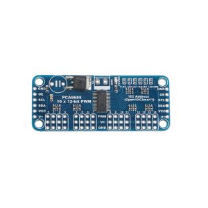
The component is typically mounted on a compact PCB module that breaks out the two independent analog outputs, making it easy to interface with development platforms like Arduino, ESP32, Raspberry Pi, and STM32 .
Key Features
-
Dual-Gang Design: Two independent 10kΩ potentiometers controlled by a single slider – ideal for stereo audio applications and dual-channel control .
-
B10K Linear Taper: 10k ohm resistance with linear response curve (B-taper), ensuring the output voltage changes proportionally to slider position .
-
Two Independent Analog Outputs: Each channel provides a separate 0-VCC analog voltage signal, allowing you to read both values independently with a microcontroller’s ADC .
-
Smooth Slide Mechanism: Provides continuous travel with excellent tactile feedback and minimal sliding noise (typically less than 68mV) .
-
Wide Operating Voltage: Compatible with 3.3V to 5V systems, suitable for both Arduino (5V) and ESP32/ESP8266 (3.3V) platforms .
-
Standard 3-Pin per Channel Interface: Each gang has three terminals (two fixed ends and one wiper), compatible with standard potentiometer wiring practices .
-
Durable Construction: Metal and plastic construction with rated mechanical life of ≥15,000 operating cycles for long-term reliability .
-
Versatile Applications: Perfect for audio mixers, lighting control, motor speed adjustment, signal processing, and user interface controls .
Technical Specifications
Pinout & Connection Guide
Standard Terminal Assignment (Per Gang)
Each of the two potentiometer gangs has three terminals, following the same pinout configuration as a standard variable resistor :
Pin Identification Tips
-
Use a Multimeter: The easiest way to identify pins is with a resistance test. Move the slider to the center position, and measure resistance between pairs of pins until you find the combination that reads the full 10kΩ value—these are the fixed ends (Terminals 1 and 2). The remaining pin is the wiper .
-
Dual-Gang Configuration: Two independent sets of three pins (six total) are controlled by the same slider. Each gang is electrically isolated from the other .
-
Wiring Diagram for Each Gang:
        Terminal 1 (VCC) ──┐
                           ├── Wiper (Output to ADC)
        Terminal 2 (GND) ──┘
⚠️ Important: The pin numbering convention may vary between manufacturers. Always verify the orientation of your specific model with a multimeter before connecting .
Usage Guide
Basic Operation Principle
The slide potentiometer acts as a variable voltage divider. When you connect the fixed ends across a voltage supply (e.g., 5V and GND), the center wiper outputs a voltage proportional to the slider position. At one end, the output is approximately 0V; at the other end, it is approximately VCC .
Wiring to Arduino Uno
Example: Reading Dual Analog Values with Arduino
This code reads both potentiometer channels and prints the values to the Serial Monitor .
Dual-Gang Slide Potentiometer Read Example
Reads both analog channels and controls LED brightness
*/
const int potPin1 = A0;
const int potPin2 = A1;
const int ledPin = 3;
int rawValue1 = 0;
int rawValue2 = 0;
void setup() {
Serial.begin(9600);
pinMode(ledPin, OUTPUT);
}
void loop() {
rawValue1 = analogRead(potPin1);
rawValue2 = analogRead(potPin2);
Serial.print("Channel A: ");
Serial.print(rawValue1);
Serial.print(" | Channel B: ");
Serial.println(rawValue2);
int brightness = map(rawValue1, 0, 1023, 0, 255);
analogWrite(ledPin, brightness);
delay(50);
}
Practical Applications
Audio Mixer / Stereo Volume Control: The dual-gang configuration is perfect for stereo audio applications where both left and right channels must be adjusted simultaneously with perfect tracking . Wire each gang as a voltage divider in the audio signal path.
Dual-Channel Signal Processing: Use the two independent outputs to control two separate parameters in your project, such as LED brightness and motor speed, or frequency and amplitude of a signal generator.
User Interface Control: The linear slide provides visual feedback of the current setting, making it ideal for DJ mixers, lighting desks, and control panels where at-a-glance status is valuable .
Test Equipment: Use in DIY oscilloscopes, function generators, or power supplies for fine adjustment of parameters.
Robotics: Implement slide potentiometers as position sensors or manual override controls for robotic arms and actuators.
Lighting Control: Perfect for controlling LED brightness or color mixing in stage lighting and architectural lighting projects .
Important Usage Considerations
-
Power Rating: Ensure the power dissipation across the potentiometer does not exceed its rated power (typically 0.25W) . For high-power applications, use the potentiometer as a control input only, not as a direct power handling device.
-
Avoid Excessive Force: Do not apply excessive force to the slider mechanism to prevent damage to the resistive track or wiper .
-
Noise Filtering: For stable ADC readings, consider adding a small capacitor (0.1µF) between the wiper and GND to filter out high-frequency noise.
Q: What does "Dual-Gang" mean on a slide potentiometer?
“Dual-gang” means the component contains two independent potentiometers operated by a single sliding mechanism . This design is essential for stereo audio applications where both left and right channels must be adjusted simultaneously with perfect tracking. Each gang provides its own separate analog output.
Q: How do I identify the pins on my dual-gang slide potentiometer?
Use a multimeter in resistance mode. Move the slider to the center position and measure resistance between pairs of pins. The combination that reads the full 10kΩ value identifies the two fixed ends (Terminals 1 and 2). The remaining pin for each gang is the wiper . Repeat for the second gang’s three pins.
Q: Can I use only one gang of a dual-gang potentiometer?
Yes, you can absolutely use just one gang and leave the other gang unconnected. Many applications use dual-gang pots as single-channel controls when the second channel is not needed . Simply wire the three pins of the gang you wish to use and ignore the other three pins.
Q: What is the difference between linear (B-taper) and logarithmic (A-taper) potentiometers?
B-taper (linear) changes resistance evenly across the slider travel, making the output voltage directly proportional to position. This is ideal for voltage dividers and general control applications. A-taper (logarithmic) changes resistance exponentially, matching the non-linear sensitivity of human hearing, and is preferred for audio volume controls .
Q: Can I connect this directly to an Arduino or ESP32?
Yes, you can connect it directly. The operating voltage range is 3.3V to 5V, making it compatible with both Arduino (5V) and ESP32/ESP8266 (3.3V) systems . Connect the outer terminals to VCC and GND, and the wiper to an analog input pin .
Q: The analog readings are jumping around. How do I fix this?
This is often due to electrical noise. Add a small capacitor (0.1µF) between the wiper (output) and GND to filter high-frequency noise . Also ensure your power supply is stable and wiring is secure.
Q: What is the typical slide travel length?
Slide travel lengths vary by model, with common options including 30mm, 45mm, 60mm, 75mm, and 100mm . Choose based on your panel size and the resolution required for your application.
Q: Is this suitable for professional audio applications like mixers?
Yes, dual-gang slide potentiometers are widely used in professional audio mixers for stereo channel faders . They provide smooth operation, excellent channel matching, and long mechanical life (≥15,000 cycles) .
Q: How do I calculate the output voltage from the potentiometer?
The output voltage follows the formula: Vout = VCC × (wiper position / total travel) for linear (B-taper) pots. When used as a voltage divider with the wiper connected to an ADC, the analog reading is directly proportional to slider position .
Q: What happens if I connect the potentiometer incorrectly?
Incorrect wiring may result in limited range (wiper not sweeping full scale) or the potentiometer becoming hot and potentially damaged . Always verify connections with a multimeter before applying power. If the pot gets hot immediately, disconnect power and check your wiring.
Q: Can I use this for motor speed control directly?
Not directly for high-power motors. The power rating (0.25W) is suitable only for low-power signal applications. For motor speed control, use the potentiometer as an input to a motor driver (e.g., L298N or MOSFET circuit) which handles the high power. The potentiometer provides the control signal to the driver.
Q: The two gangs are not reading identical values. Is this normal?
Small variations between gangs are normal due to manufacturing tolerances (±20% for total resistance). However, both gangs should track proportionally as you move the slider. For critical applications, you can calibrate the readings in software .