Product Overview
The ESP8266 Serial WiFi Module Adapter Plate is an essential breakout board designed to solve the common problem of working with SMD (Surface Mount Device) ESP8266 modules such as the ESP-07, ESP-08, and ESP-12E. These popular Wi-Fi modules feature an unfriendly 2mm pin pitch that is incompatible with standard breadboards (which use 2.54mm spacing) and difficult to solder for prototyping .
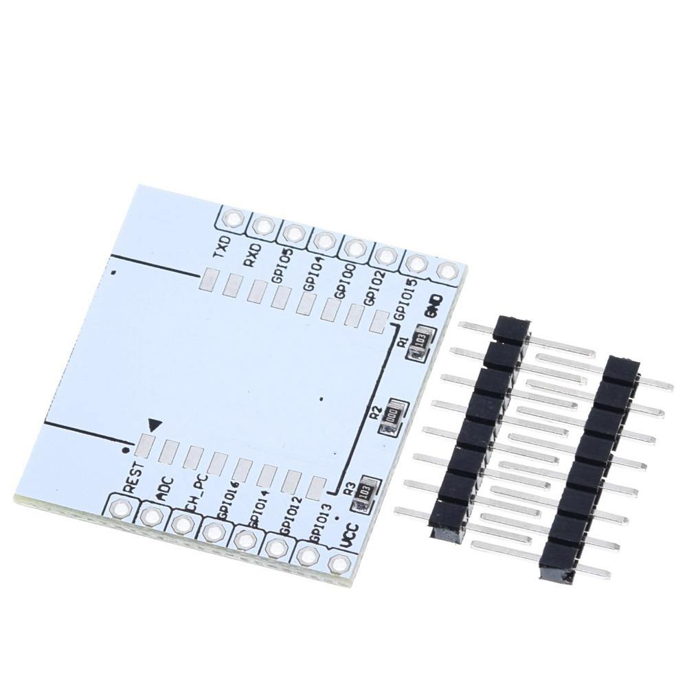
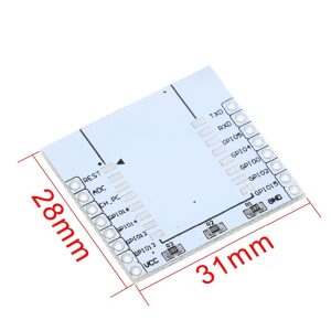
This adapter plate transforms these SMD modules into a breadboard-friendly format, converting the 2mm pitch to the standard 2.54mm spacing used by breadboards, perfboards, and standard jumper wires . The WiFi module solders directly to the adapter, with clearly labeled pinouts on the top layer for easy identification and connection .
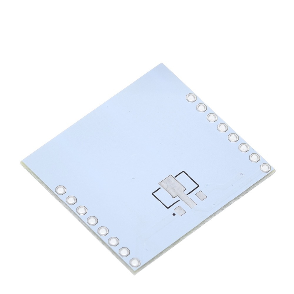
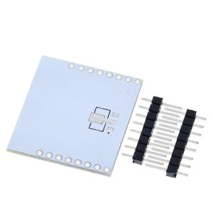
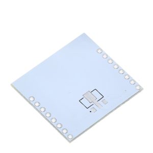
Beyond simple pin conversion, the adapter plate includes thoughtful engineering features to simplify your project. It features a reserved land-pattern for a 3.3V voltage regulator on the bottom layer, allowing you to add onboard voltage regulation if needed . A pre-populated 10K pull-up resistor ensures proper chip operation by connecting CH_PD (Chip Enable) to VCC . Additionally, GPIO15 is connected to GND to facilitate normal flash boot mode, eliminating one of the common wiring errors when working with ESP8266 modules .
Whether you are a hobbyist prototyping on a breadboard, an educator building classroom kits, or a business developing custom IoT products, this adapter plate provides a reliable, reusable platform for integrating ESP8266 Wi-Fi modules into your projects without the hassle of custom PCB design.
Key Features
-
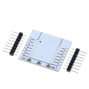
Pin Pitch Conversion: Converts the 2mm pin pitch of ESP-07/08/12 modules to the standard 2.54mm (0.1-inch) breadboard-friendly spacing, allowing direct use with breadboards, perfboards, and standard jumper wires .
-
Wide Module Compatibility: Compatible with multiple ESP8266 SMD modules including ESP-07, ESP-08, ESP-12, ESP-12E, and ESP-12F .
-
Reserved 3.3V Voltage Regulator Land-Pattern: Features a dedicated area on the bottom layer for soldering a 3.3V voltage regulator (e.g., AMS1117-3.3). When the 0Ω jumper resistor is removed, the VCC pin accepts 4.5V–9V input, which is regulated down to 3.3V for the module .
-
Pre-Populated Pull-Up Resistor: Includes a 10K pull-up resistor between CH_PD (Chip Enable) and VCC to ensure the chip is properly enabled during normal operation .
-
Integrated Boot Configuration: GPIO15 is connected to GND on the PCB, which is required for proper boot mode operation, eliminating one common wiring error .
-
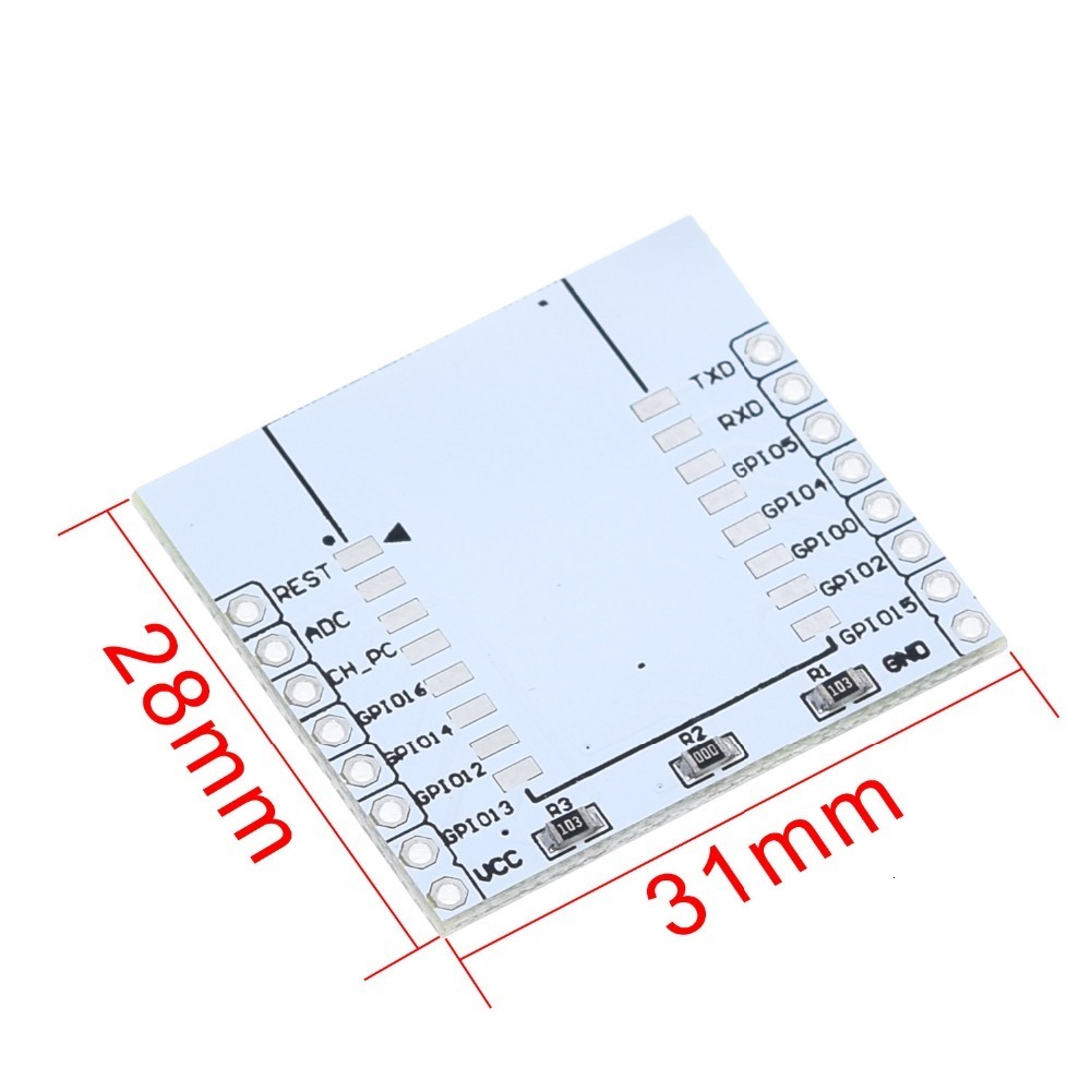
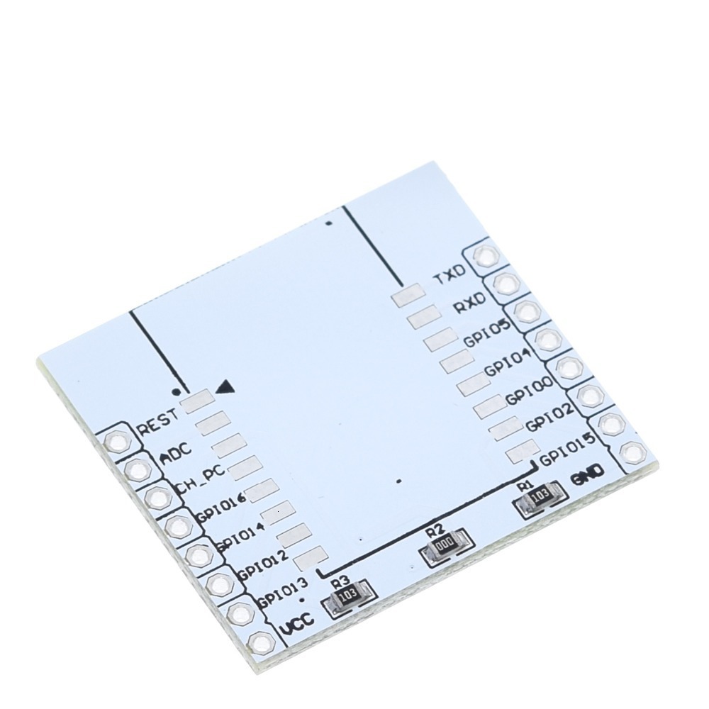
Clear Pin Labeling: Pinouts are clearly printed on the top layer of the PCB in black for easy identification and connection .
-
Compact and Durable Design: PCB dimensions approximately 27mm × 30mm × 1.6mm, with a sturdy white or black solder mask finish .
-
Ideal for Prototyping: Perfect for use with breadboards, perfboards, and for creating reusable module sockets for multiple projects.
Technical Specifications
Q: What ESP8266 modules are compatible with this adapter plate?
This adapter plate is compatible with the ESP-07, ESP-08, ESP-12, ESP-12E, and ESP-12F modules . These are the common SMD ESP8266 modules with a 2mm pin pitch.
Q: Why do I need an adapter plate for ESP modules?
ESP modules like the ESP-12E use a 2mm pin pitch, while standard breadboards and perfboards use 2.54mm (0.1 inch) spacing. This makes it impossible to plug them directly into a breadboard. The adapter plate converts the spacing to the standard 2.54mm pitch, making prototyping much easier
Q: Does the adapter plate include the voltage regulator?
No. The adapter plate includes a reserved land-pattern for a 3.3V voltage regulator, but the regulator itself is not included. You must supply and solder your own regulator if you want onboard voltage regulation
Q: What is the purpose of the 0Ω jumper resistor?
The 0Ω jumper resistor (often labeled R1 or R2) connects the VCC pin directly to the module’s 3.3V supply. To use the onboard 3.3V regulator, you must desolder this resistor so that the regulator can supply power to the module instead
Q: What type of voltage regulator should I use with this adapter?
Use a 3.3V low-dropout regulator (LDO) such as the AMS1117-3.3 or LM1117-3.3. Ensure the regulator can supply at least 300mA to reliably power the ESP8266 module
Q: How much current does the ESP8266 module require?
The ESP8266 requires a stable 3.3V supply with at least 250mA–300mA for reliable operation, especially during Wi-Fi transmission peaks . The 3.3V output from many USB-to-TTL adapters is often insufficient.
Q: Can I power the ESP8266 from a 5V Arduino?
No. The ESP8266 is not 5V tolerant. Applying 5V to the VCC pin or any GPIO pin will permanently damage the module . You must use a 3.3V regulator and, for signals, a logic level converter if interfacing with 5V devices.
Q: Why does my ESP module keep resetting when Wi-Fi turns on?
This is almost always a power supply issue. Wi-Fi transmission causes current spikes that can exceed 250mA. Ensure your power supply can deliver sufficient current and that your wiring is short and secure. Adding a 100µF electrolytic capacitor near the module can also help
Q: What is the recommended power supply for prototyping with this adapter?
A 3.3V regulated power supply with at least 500mA capacity is recommended. Alternatively, you can use the onboard regulator with a 5V–9V DC input (after desoldering the 0Ω jumper and installing a regulator)
Q: How do I put the ESP module into programming mode?
To enter programming (UART download) mode :
-
Pull GPIO0 LOW (connect to GND)
-
Ensure GPIO15 is LOW (already connected on adapter)
-
Ensure GPIO2 is HIGH (internal pull-up)
-
Ensure EN/CH_PD is HIGH (connected via 10K resistor on adapter)
-
Apply power or pulse RST LOW
-
The module is now ready to receive firmware
Q: Why can't I upload code to my ESP module?
Common issues include:
-
GPIO0 not held LOW during power-on/reset
-
Insufficient power supply (USB-to-TTL adapters often provide too little current)
-
Incorrect serial connections (TX to RX, RX to TX)
-
Missing 3.3V supply (do not use 5V)
-
GPIO15 not LOW (this is handled by the adapter)
Q: What is the default boot mode when using this adapter?
With the adapter’s built-in configuration (GPIO15 LOW, GPIO2 HIGH via internal pull-up, GPIO0 HIGH unless manually pulled LOW), the module will boot into Flash Boot (Normal Operation) mode by default
Q: Why is there a 10K resistor on the board?
The 10K resistor acts as a pull-up between CH_PD (Chip Enable) and VCC. This ensures the chip is properly enabled for normal operation
Q: Do I need to add any additional components for the module to work?
The adapter plate includes the essential pull-up resistor (10K) and connects GPIO15 to GND. For stable operation, you should add a 100µF electrolytic capacitor across VCC and GND to smooth out power supply fluctuations during Wi-Fi transmission
Q: What can I build with this adapter plate and an ESP module?
Popular projects include:
-
Smart home devices (lighting control, smart plugs, sensors)
-
IoT data loggers and weather stations
-
Wireless sensor networks
-
Remote control systems
-
Custom Wi-Fi-enabled products
Q: Is this adapter suitable for use in final products, or only for prototyping?
The adapter is primarily designed for prototyping and development. For final products, a custom PCB is typically recommended for optimal space and reliability. However, for low-volume production or educational kits, the adapter can be used as a permanent module carrier.
Q: Can I use this adapter with ESP-01 modules?
No. ESP-01 modules have a different pin configuration (8-pin DIP) and are not compatible with this adapter. This adapter is designed specifically for ESP-07, ESP-08, and ESP-12 series modules