
Device Pinout & Schematics
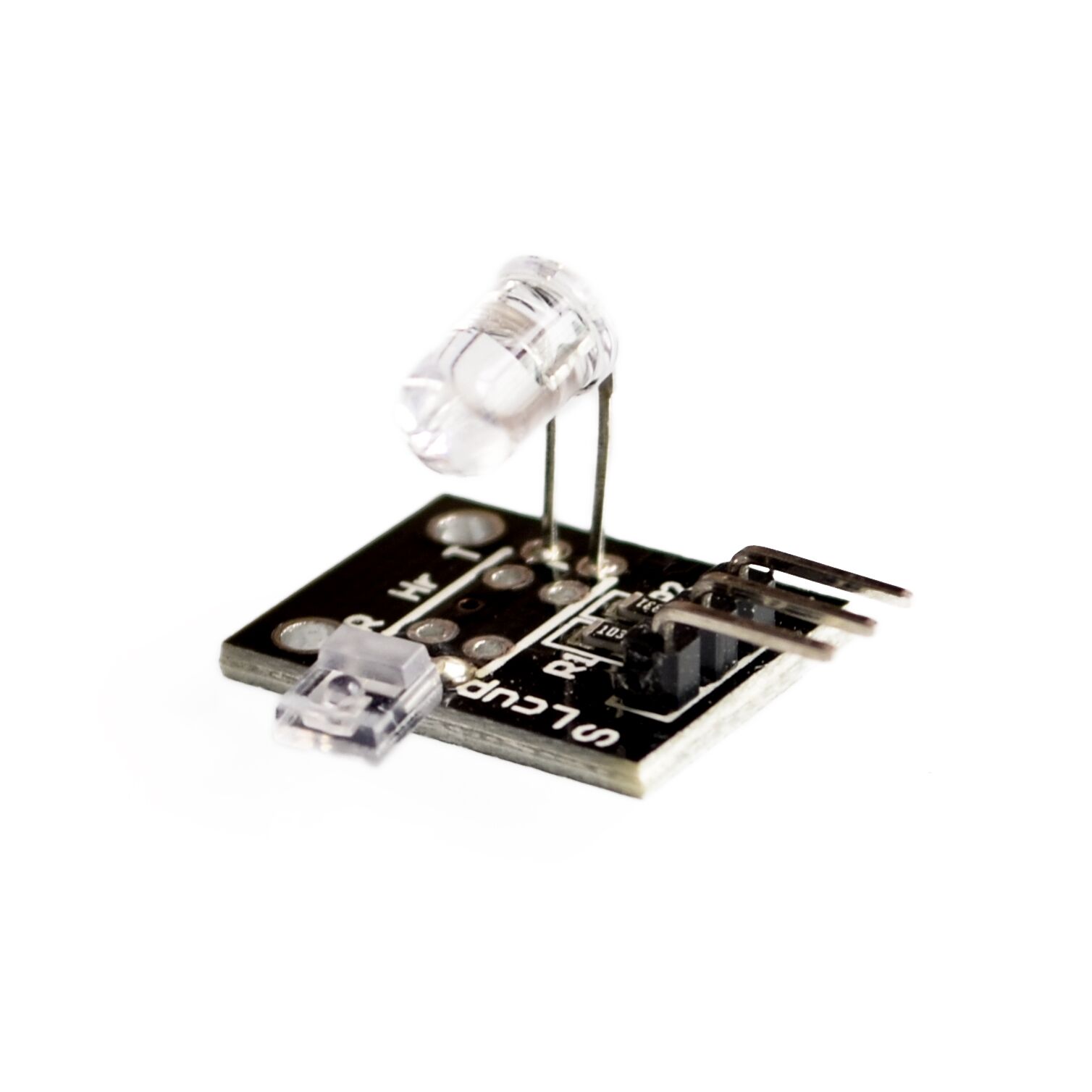
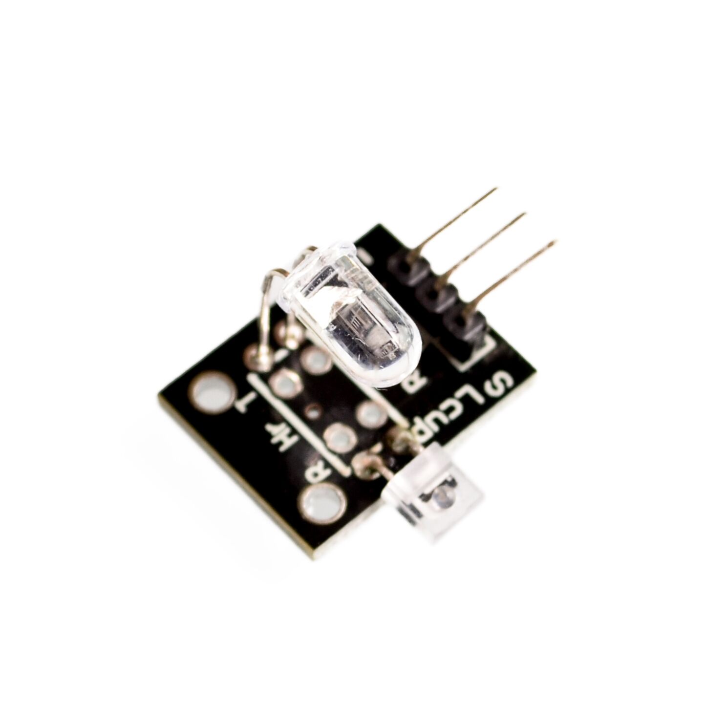
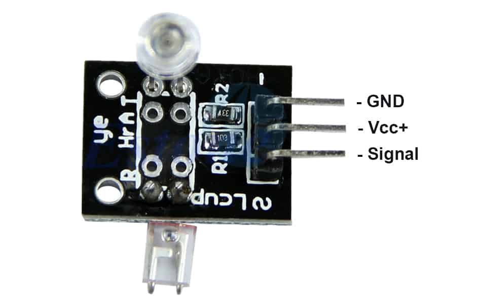
This module has three pins: GND, Vcc+, and Signal. The pinout is as follows:
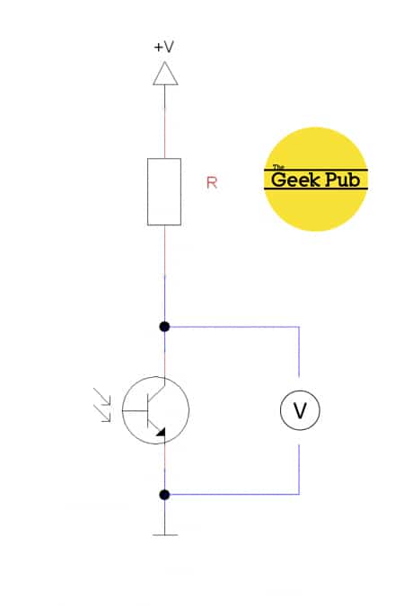
The KY-039 heartbeat sensor schematic is as follows:
Our Projects that Use this Sensor
We do not currently have any Geek Pub projects that use the heartbeat sensor. We will be creating one soon though so check back!
Code Examples
You’ll find below code examples of using the KY-039 heartbeat sensor with both Arduino and Raspberry Pi (Python).
KY-039 Heartbeat Sensor Code Example for Arduino
The following code example is for the Arduino. This code will read the Analog Output Sensor value and write it to the serial console, pause 500ms and repeat.
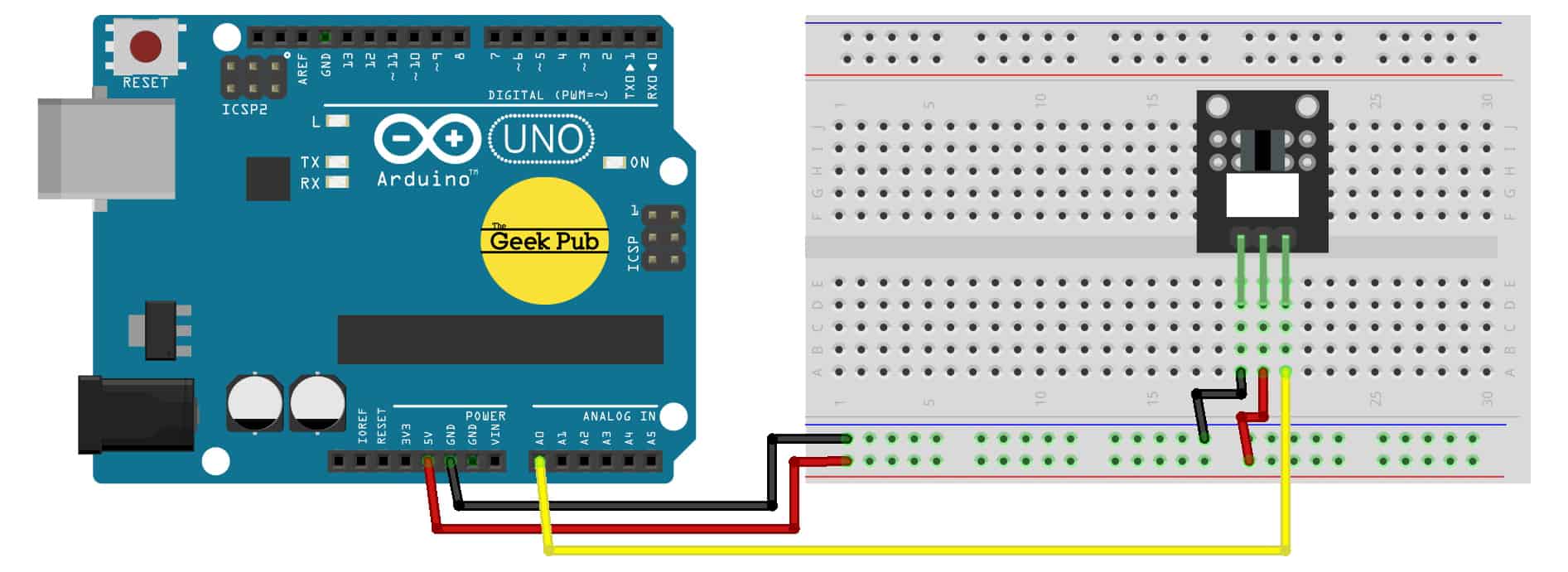
Arduino Wiring:
- KY-039 Sensor GND to Arduino GND
- KY-039 Sensor Signal to Arduino PIN A0
- KY-039 Sensor Vcc+ to Arduino +5V