Product Overview
The FT232RL USB to RS232 Converter is a professional-grade, 6-pin download cable designed to bridge the gap between your computer’s USB port and RS232 serial devices. Powered by the industry-leading FTDI FT232RL chip, this converter provides a reliable, high-performance solution for programming, debugging, and communicating with a wide range of embedded systems, routers, and industrial equipment .
Unlike cheaper converters that use generic chips, the FT232RL is the gold standard for USB-to-serial conversion. It is widely used by engineers and developers for its exceptional driver stability, broad operating system support, and robust performance at high baud rates. The chip integrates a USB 2.0 full-speed controller, UART, and all necessary support components—including an internal EEPROM and clock circuit—into a single compact package, eliminating the need for external components and ensuring reliable plug-and-play operation. .
The black-colored cable features a 6-pin interface, providing essential communication lines (TXD, RXD) along with hardware flow control signals (RTS, CTS) and DTR for auto-reset functionality. This makes it an ideal tool for programming Arduino Pro Mini, ESP8266, ESP32, STM32, and STC microcontrollers, as well as accessing console ports on routers, switches, and other network equipment .
With support for baud rates up to 3 Mbps and selectable 3.3V or 5V TTL logic levels, this converter is compatible with both modern low-voltage devices and legacy 5V systems. The built-in EEPROM stores USB configuration parameters, and the unique FTDIChip-ID™ feature provides a built-in security dongle capability for anti-cloning protection .
Key Features
-
FTDI FT232RL Chipset: Genuine FTDI chip ensuring superior driver stability, wide OS compatibility, and reliable high-speed communication .
-
6-Pin RS232 Interface: Full set of signals including TXD, RXD, RTS, CTS, DTR, and GND for complete hardware flow control and auto-reset capability .
-
High-Speed Data Transfer: Supports baud rates from 300 bps up to 3 Mbps, enabling fast firmware flashing, real-time debugging, and high-speed data logging .
-
Dual-Voltage TTL Levels: Configurable 3.3V or 5V logic level output to match your target device’s requirements—safe for both 3.3V and 5V systems .
-
Built-in EEPROM: 256-byte internal EEPROM configures USB VID, PID, serial number, and product description strings for flexible device identification .
-
Integrated Clock Generator: Internal clock eliminates the need for external crystals; can output 6MHz, 12MHz, 24MHz, or 48MHz to drive external logic .
-
FTDIChip-ID™ Security Feature: Unique, factory-programmed serial number per device readable over USB—enables anti-cloning protection in commercial applications .
-
Onboard TX/RX LEDs: Visual indicators for transmit and receive activity provide real-time feedback of data transmission status.
-
Plug-and-Play Cross-Platform: Native driver support for Windows 7/8/10/11, macOS, Linux, and Android—no complex driver hunting required .
-
Asynchronous & Synchronous Bit-Bang Modes: Configurable interface modes for SPI, I2C, and JTAG communication using the Multi-Protocol Serial Engine (MPSSE) .
Technical Specifications
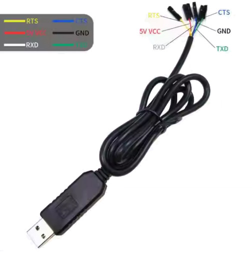
Pinout & Connection Guide
The 6-pin interface uses standard colors for easy identification. Always verify wiring with a multimeter if unsure.
Colors may vary by manufacturer—verify labeling on your specific cable.
Critical Connection Rules:
-
TXD → Target RX (Transmit from cable goes to Receive on target)
-
RXD → Target TX (Receive on cable comes from Transmit on target)
-
Always connect GND to target ground
-
Select correct voltage (3.3V or 5V) before connecting to target device
-
DTR with capacitor provides auto-reset for Arduino-compatible boards
Usage Guide
Driver Installation
The FT232RL is renowned for its excellent driver support. Drivers are available for all major operating systems from the FTDI Chip website .
Windows 7/8/10/11:
-
Download the latest “CDM (Combined Driver Model)” from the FTDI website .
-
Run the installer (CDM v2.12.36 WHQL Certified.exe) with Administrator privileges.
-
Connect the converter to your computer.
-
Verify installation in Device Manager → Ports (COM & LPT) → “USB Serial Port (COMx)” .
Driver Compatibility Notes:
-
The FT232RL has dedicated drivers for Windows 7, 8, 10, and 11 .
-
Drivers for Windows 98/2000/XP/Vista are also available for legacy systems .
-
For Windows 10/11, the driver automatically installs via Windows Update in most cases.
macOS:
Linux:
Android:
Wiring Instructions
Connecting to Arduino Pro Mini / Nano:
Connecting to ESP32 / ESP8266 (3.3V logic):
Connecting to STC Microcontroller:
Auto-Reset for Arduino (DTR with Capacitor)
The DTR signal provides auto-reset functionality for Arduino-compatible boards. Connect DTR to the target’s RESET pin through a 100nF (0.1µF) capacitor :
Converter DTR ---|| (100nF capacitor) --- Target RST
This capacitor creates a brief LOW pulse on the RESET line when DTR is toggled, triggering the bootloader without manual button pressing .
Loopback Test (Functionality Verification)
To verify the converter is working correctly:
-
Connect TXD and RXD pins together using a jumper wire.
-
Open a serial terminal program (PuTTY, Arduino Serial Monitor, CoolTerm).
-
Select the converter’s COM port.
-
Set baud rate to 115200, 8 data bits, 1 stop bit, no parity.
-
Type characters—they should be echoed back to the terminal .
If characters echo correctly, both transmit and receive paths are functional.
STC Microcontroller “Cold Start” Programming
When programming STC series microcontrollers:
-
Ensure all connections are secure (GND, VCC, TXD, RXD).
-
In STC-ISP software, select the correct COM port.
-
Load your HEX file.
-
Click Download/Program.
-
Power off the target board (disconnect VCC).
-
Power on the target board within 2 seconds (cold start).
-
Wait for “Operation Success” message.
Router / Switch Console Access
For accessing console ports on routers and switches:
Important: Do NOT connect the 5V/3.3V power lines—routers and switches are powered separately.
Using with TTL-Level Devices (3.3V or 5V)
The FT232RL supports multiple logic levels via the VCCIO pin :
The logic level must match the target device’s specifications to prevent damage.
Q: Why choose an FT232RL-based converter over cheaper CH340 or PL2303 alternatives?
The FT232RL is widely regarded as the industry standard for USB-to-serial conversion. It offers superior driver stability across all operating systems, native support without complex driver hunting, and reliable performance at high baud rates . Unlike clone chips that may have driver issues, FTDI provides ongoing driver updates and technical support. The chip also features unique capabilities like the built-in security dongle (FTDIChip-ID™) and integrated clock generator, making it suitable for both development and commercial products .
Q: What's the difference between the FT232RL and FT232R?
The FT232RL is a specific package variant of the FT232R. The “L” indicates the 28-pin SSOP package type. Both share the same core functionality—there is no functional difference between the two designations .
Q: Is this converter compatible with Windows 10/11?
Yes. The FT232RL has fully certified drivers for Windows 7, 8, 10, and 11. FTDI maintains current drivers for all modern Windows versions .
Q: What is the maximum cable length recommended for RS232 communication?
For RS232 communication at standard baud rates (up to 115200), cable lengths up to 15 meters (50 feet) are generally acceptable. For higher baud rates or noisy environments, shorter cables (3-5 meters) are recommended to maintain signal integrity.
Q: Can this converter power my target device directly?
Yes, within USB limits. The 5V line can provide up to 500mA (standard USB 2.0 specification). The 3.3V output provides regulated 3.3V at lower current (typically 50-100mA). This is sufficient for low-power microcontrollers (Arduino Pro Mini, bare STM32, ESP8266 without Wi-Fi). For power-hungry devices (motors, servos, ESP32 with active Wi-Fi), use a separate external power supply
Q: Does this converter support RS232 voltage levels (±12V) or TTL levels (3.3V/5V)?
This converter outputs TTL logic levels (3.3V or 5V), not RS232 voltage levels (±12V). It is designed to connect directly to microcontrollers and TTL-level devices. To connect to true RS232 ports (like old PC serial ports), you need an additional level shifter (e.g., MAX232).
Q: My computer doesn't recognize the device. What should I do?
Follow this checklist:
-
Ensure drivers are properly installed (download from FTDI website) .
-
Try a different USB port on your computer.
-
Try a different USB cable—some cables are charge-only and lack data lines.
-
Check Device Manager for yellow exclamation marks .
-
If the device has been previously used, try uninstalling and reinstalling the driver.
-
Test on another computer to isolate the issue.
Q: How do I install FT232RL drivers on Windows?
The easiest method is to let Windows Update handle it automatically—drivers will install when you connect the module . Alternatively, download the “CDM (Combined Driver Model)” from the FTDI website and run the installer as Administrator .
Q: The device shows as "FT232R USB UART" but has a yellow exclamation mark. How do I fix it?
This indicates a driver issue. Right-click the device in Device Manager → Update Driver → Browse my computer → Let me pick from a list → Select the FTDI driver version that matches your OS. If that fails, uninstall the device, restart your computer, and reinstall the driver from scratch.
Q: What are the recommended serial terminal settings for first-time use?
For initial testing, use these default settings:
-
Baud Rate: 115200
-
Data Bits: 8
-
Stop Bits: 1
-
Parity: None
-
Flow Control: None
These settings work with most Arduino, ESP32, and STM32 devices .
Q: How do I change the COM port number assignment in Windows?
In Device Manager:
-
Expand Ports (COM & LPT)
-
Right-click “USB Serial Port (COMx)”
-
Select Properties → Port Settings → Advanced
-
Choose a new COM port number from the dropdown list
-
Click OK
Q: What can I build with this FT232RL converter?
Popular applications include:
-
Embedded development: Programming Arduino, ESP8266, ESP32, STM32
-
Router firmware flashing: OpenWrt, DD-WRT installation and recovery
-
Serial console access: Debugging Raspberry Pi and other SBCs without a monitor
-
STC microcontroller programming: 51-series development
-
Industrial equipment: PLC programming, serial instrument communication
-
GPS module interfacing: Reading NMEA data on PC
-
Hardware debugging: Monitoring UART output from any embedded device
Q: How does the auto-reset feature work with DTR and the capacitor?
When uploading code to Arduino boards, the IDE toggles the DTR line. Connecting DTR to the target’s RESET pin through a 100nF capacitor creates a brief LOW pulse that triggers the bootloader. The capacitor is essential—direct connection causes improper timing and upload failures . Many development boards have this capacitor built-in; for bare chips or Pro Mini, you must add it externally.
Q: Why are the TX/RX LEDs not blinking?
The LEDs blink only during active data communication:
-
At lower baud rates, they blink slowly
-
At high baud rates (>115200), they may appear constantly dim or always lit
-
If no data is being transmitted, LEDs remain off
-
Perform a loopback test (connect TXD to RXD) to verify functionality
Q: I'm getting garbage characters in my terminal. What's wrong?
Common causes and solutions:
-
Baud rate mismatch—ensure terminal baud rate matches target device (common: 9600, 115200, 57600)
-
Data format mismatch—typically 8 data bits, 1 stop bit, no parity
-
TXD/RXD swapped—swap the TX and RX connections
-
Voltage level mismatch—verify 3.3V/5V setting matches target logic level
-
Ground not connected—ensure GND is connected between devices
Q: The converter works for a while but then disconnects. What's the issue?
This can be caused by:
-
Insufficient power—target device drawing too much current from USB
-
Driver conflict—another application using the same COM port
-
USB selective suspend—disable USB power management in Windows Device Manager
-
Loose connection—check USB and target connections
Q: Is this converter compatible with Raspberry Pi for serial console access?
Yes. Connect:
-
Converter GND → Raspberry Pi GND (Pin 6)
-
Converter TXD → Raspberry Pi RXD (Pin 10)
-
Converter RXD → Raspberry Pi TXD (Pin 8)
Do NOT connect the 5V or 3.3V lines—power the Pi separately via USB-C or GPIO 5V. The Pi’s UART uses 3.3V logic, which is compatible with the converter’s 3.3V output .
Q: Can I use this converter for JTAG or SPI programming?
The FT232RL supports Multi-Protocol Serial Engine (MPSSE) which allows emulation of SPI, I2C, and JTAG protocols. However, this requires custom firmware and specific software support. For most users, standard UART mode (TXD/RXD) is used for programming and debugging .