Product Overview
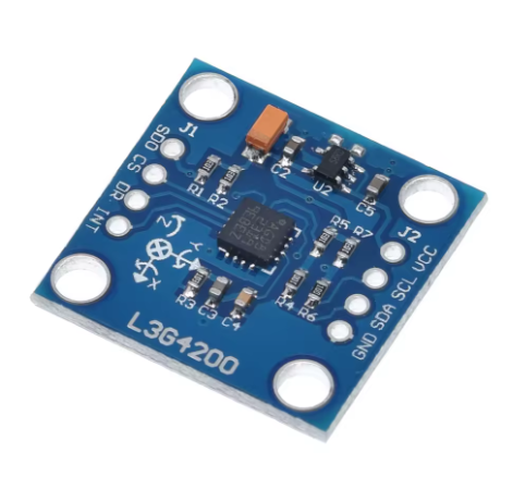
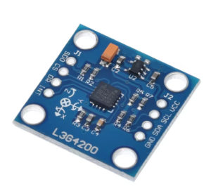
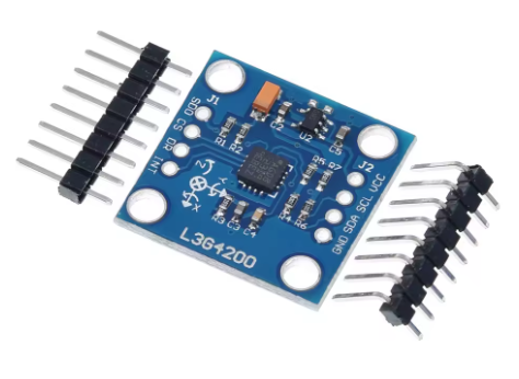
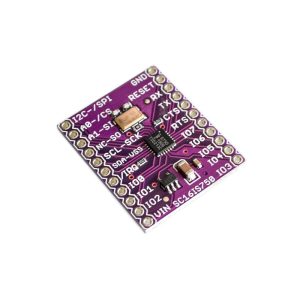
The GY-50 L3G4200D 3-Axis Gyroscope Module is a high-performance digital angular rate sensor designed for measuring rotational velocity along the X (Pitch), Y (Roll), and Z (Yaw) axes . Based on STMicroelectronics’ advanced MEMS (Micro-Electro-Mechanical Systems) technology, this module provides precise, drift-resistant measurements for motion tracking and stabilization applications.
The L3G4200D sensor features an ultra-stable 16-bit rate-value data output, offering three user-selectable full-scale ranges of ±250, ±500, or ±2000 degrees per second (dps) . This flexibility allows you to optimize sensitivity for specific applications—from slow human motion tracking to high-speed robotics and drone flight control.
With a wide operating voltage range of 2.4V to 3.6V and low current consumption of just 6.1mA, the GY-50 module is designed for low-power applications . The breakout board also includes an onboard 3.3V voltage regulator, making it compatible with both 3.3V and 5V microcontrollers like Arduino, ESP32, and Raspberry Pi.
The sensor features an embedded temperature sensor for drift compensation, adjustable bandwidth from 100Hz to 800Hz, and supports both I2C and SPI digital interfaces for flexible communication . Whether you’re building a self-balancing robot, a quadcopter flight controller, a VR headset, or a vehicle stability system, the GY-50 L3G4200D module delivers accurate, reliable angular velocity data.
Key Features
-
3-Axis Angular Rate Sensing: Measures rotation around X (Pitch), Y (Roll), and Z (Yaw) axes simultaneously .
-
Selectable Full-Scale Ranges: User-selectable measurement ranges of ±250 dps, ±500 dps, and ±2000 dps for high sensitivity or high-speed rotation capture .
-
16-Bit Digital Output: Provides 16-bit resolution with sensitivity options ranging from 8.75 to 70 LSB per degree per second .
-
Dual Communication Interfaces: Supports both I2C (up to 400 kHz) and SPI (up to 10 MHz) protocols for flexible connectivity .
-
Wide Power Compatibility: Accepts 3V–5V DC input; compatible with both 3.3V and 5V microcontrollers thanks to onboard voltage regulation .
-
Low Power Consumption: Operates at just 6.1mA active current, with power-down and sleep modes for battery-powered applications .
-
Adjustable Bandwidth: Configurable output data rates from 100Hz to 800Hz, allowing optimization for different motion dynamics .
-
Embedded Temperature Sensor: On-chip temperature sensor aids in thermal drift compensation for stable measurements .
-
High Shock Survivability: Rugged MEMS design capable of withstanding high mechanical shocks, suitable for demanding environments .
-
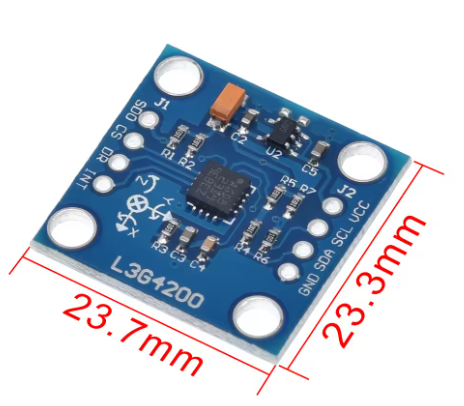
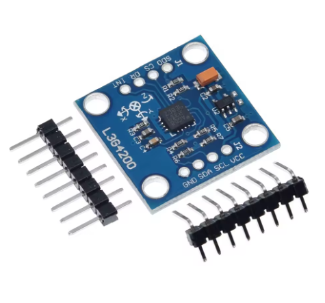
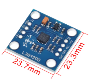
Compact Module Size: 23mm × 23mm form factor with mounting holes for easy integration into projects .
Technical Specifications
Pinout & Connection Guide
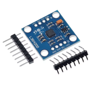
Pin Definitions
Note: Pin labeling may vary slightly between GY-50 board versions. Always verify the silkscreen on your specific module .
I2C Mode Wiring (Recommended – 2 pins)
For I2C communication, connect the CS pin to VCC (3.3V or 5V) to disable SPI mode and enable I2C .
SPI Mode Wiring (Faster – 4 pins)
For higher data rates, use SPI communication .
Usage Guide
Understanding Gyroscope Measurements
Gyroscopes measure angular velocity – the speed of rotation around an axis. The output is typically in degrees per second (°/s). Positive values indicate rotation in one direction (e.g., clockwise), while negative values indicate the opposite direction .
*Note: Unlike accelerometers, gyroscopes measure rate of rotation, not orientation. To determine absolute angle, you must integrate the gyroscope output over time (the sensor measures angular velocity, and angle = angular velocity × time).
Configuring the Full-Scale Range
The L3G4200D offers three selectable ranges, chosen through its control registers:
Software Setup (Arduino IDE)
Step 1: Install Required Libraries
Several libraries support the L3G4200D. The most commonly used is the “L3G4200D” library by “Fusion”.
-
Open Arduino IDE → Sketch → Include Library → Manage Libraries
-
Search for “L3G4200D”
-
Install the library (e.g., by “Fusion” or “Pololu”)
Step 2: Basic Gyroscope Read Example (I2C)
GY-50 L3G4200D Basic Gyroscope Read Example
Reads angular velocity on X, Y, and Z axes
*/
#include <Wire.h>
#include <L3G4200D.h>
L3G4200D gyro;
void setup() {
Serial.begin(9600);
Wire.begin();
if (!gyro.init()) {
Serial.println("Failed to initialize GY-50 sensor. Check wiring!");
while (1);
}
gyro.setFullScale(L3G4200D_FULLSCALE_2000);
gyro.setODR(L3G4200D_ODR_400HZ);
Serial.println("GY-50 L3G4200D Gyroscope Ready");
}
void loop() {
gyro.read();
int x = gyro.x();
int y = gyro.y();
int z = gyro.z();
float x_dps = x / 70.0;
float y_dps = y / 70.0;
float z_dps = z / 70.0;
Serial.print("X: ");
Serial.print(x_dps);
Serial.print(" dps\tY: ");
Serial.print(y_dps);
Serial.print(" dps\tZ: ");
Serial.print(z_dps);
Serial.println(" dps");
delay(100);
}
Step 3: Simple Angle Calculation (Integration)
To estimate angle from gyroscope data, integrate angular velocity over time:
float angle = 0;
unsigned long lastTime = micros();
void updateAngle(float gyroRate_dps) {
unsigned long now = micros();
float dt = (now - lastTime) / 1000000.0;
lastTime = now;
angle += gyroRate_dps * dt;
}
Note: Gyroscopes experience drift over time. For stable absolute orientation, combine gyroscope data with accelerometer data using a complementary filter or sensor fusion algorithm (e.g., Mahony or Madgwick filter).
Step 4: Interrupt Configuration Example
The INT1 pin can be configured to trigger on various events, such as data ready:
gyro.writeRegister(L3G4200D_CTRL_REG3, 0x08);
Then in your main loop, you can wait for the interrupt before reading:
pinMode(interruptPin, INPUT);
attachInterrupt(digitalPinToInterrupt(interruptPin), gyroDataReady, RISING);
Power Management
To enter power-down mode, set the appropriate bit in the control register:
gyro.writeRegister(L3G4200D_CTRL_REG1, 0x00);
Q: What is the difference between a gyroscope and an accelerometer?
A gyroscope measures angular velocity (rate of rotation) in degrees per second. An accelerometer measures linear acceleration, including gravity, in g-force. Gyroscopes are better for tracking rotation, while accelerometers are used for detecting tilt and linear motion. For full 6‑DOF orientation tracking (absolute heading), both sensors are used together.
Q: Is the GY-50 L3G4200D compatible with 5V microcontrollers like Arduino Uno?
Yes. The module operates on 3V–5V power and includes a voltage regulator, making it directly compatible with 5V systems. However, the sensor core runs at 3.3V, but the onboard circuitry handles level conversion. You can connect it directly to a 5V Arduino .
Q: Can I use this sensor with ESP32 or ESP8266?
Yes. The GY-50 module works with 3.3V logic and can be powered directly from the ESP32/ESP8266 3.3V pin. Use the same I2C or SPI pins for communication.
Q: What are the three selectable full-scale ranges for?
The ±250 dps range offers the highest sensitivity for slow, precise rotations (e.g., human gesture tracking). The ±2000 dps range allows measuring very fast rotations (e.g., drone spins or high-speed robotics). Choose the range that best matches your application’s expected angular velocity .
Q: How do I select between I2C and SPI communication?
The mode is selected by the CS pin :
Q: What does the scale factor (sensitivity) mean?
The scale factor (e.g., 70 LSB per °/s for the ±2000 dps range) tells you how to convert raw digital readings into angular velocity. For the highest range (±2000 dps), a raw reading of 70 means you are rotating at 1 degree per second .
Q: Why does my calculated angle drift over time?
Gyroscopes measure rate of rotation, not absolute angle. To get angle, you integrate the rate over time. Even small errors in the rate measurement accumulate (integrate) into increasingly large angle errors. To correct this drift, you must combine gyroscope data with accelerometer data (for tilt) and/or magnetometer data (for yaw) using a sensor fusion algorithm .
Q: What is the purpose of the INT1 pin?
The INT1 pin is a programmable interrupt output. It can be configured to trigger on various events, including:
-
Data Ready: New measurement available
-
High/Low Threshold: Angular rate exceeds a set value
-
Wake-Up: Motion detection
This allows you to offload processing from your main microcontroller and enter low-power modes until an event occurs .
Q: Can I use this sensor to build a compass or measure absolute direction (yaw)?
No. The L3G4200D is a gyroscope and measures only the rate of rotation (how fast you are turning). To get absolute heading (yaw), you need to integrate the gyroscope’s output. However, this integration leads to drift over time. For stable yaw measurement, you need a magnetometer (electronic compass) or use sensor fusion with both gyroscope and accelerometer/magnetometer data.
Q: What are typical applications for the GY-50 L3G4200D module?
Common applications include:
-
Quadcopter and drone flight controllers (stabilization)
-
Self-balancing robots and hoverboards (tilt detection)
-
GPS navigation systems (dead reckoning)
-
Virtual reality input devices (head tracking)
-
Robotics (joint angle monitoring)
-
Vehicle stability control systems (rollover detection)
-
3D simulation and gaming (motion controllers)