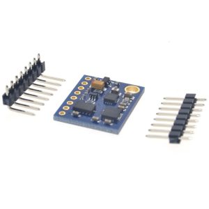
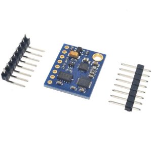
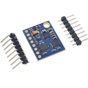
Product Overview
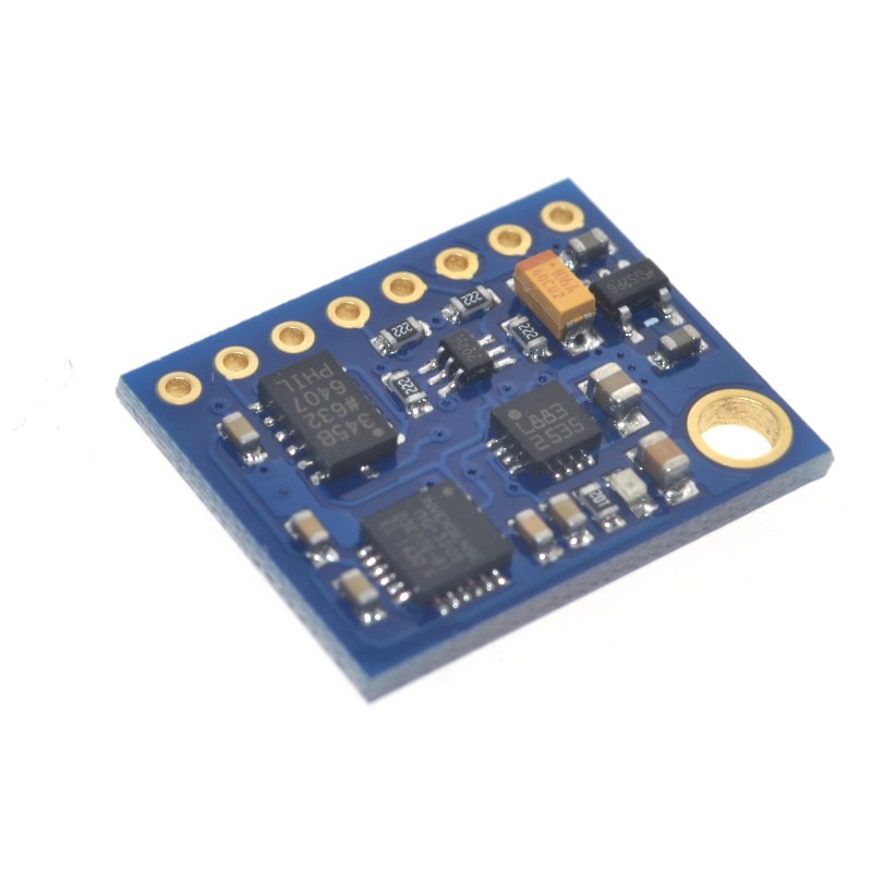
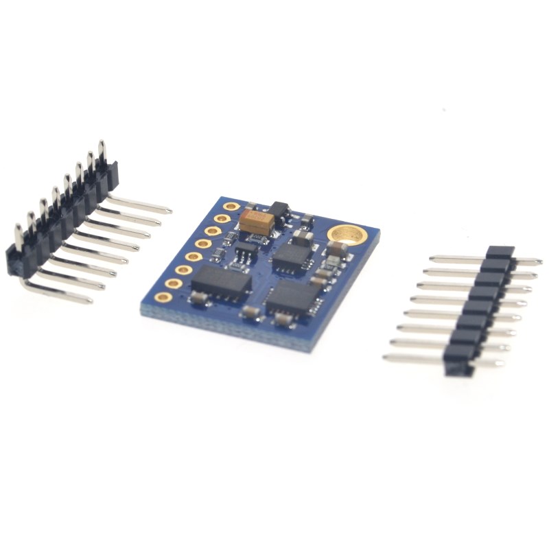
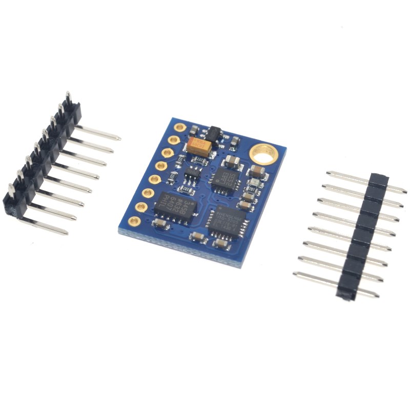
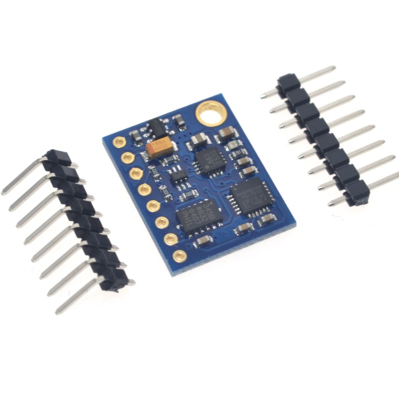
The GY-85 IMU 9-Axis Sensor Module is a complete motion-tracking solution that integrates three high-performance MEMS sensors on a single compact board: a 3-axis gyroscope (ITG3205/ITG3200) , a 3-axis accelerometer (ADXL345) , and a 3-axis magnetometer (HMC5883L) . This combination provides 9 degrees of freedom (9DOF) for precise orientation, motion, and heading detection.
Unlike single-sensor modules, the GY-85 fuses gyroscope, accelerometer, and magnetometer data to deliver stable, drift-free 3D orientation (yaw, pitch, and roll). It is widely used in drones (UAVs), quadcopters, robotics, head-tracking systems, gaming controllers, and inertial navigation systems.
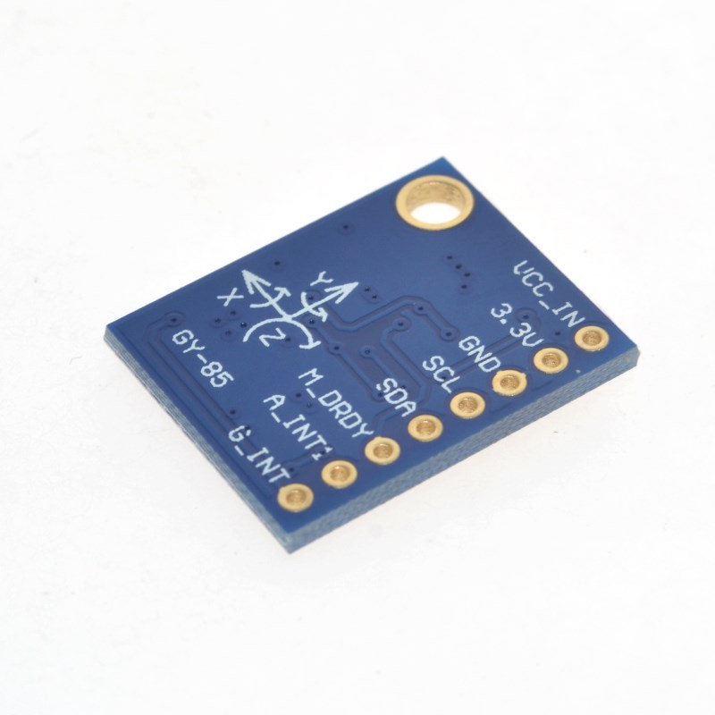
All three sensors communicate via the I2C protocol, requiring only two data lines (SDA and SCL) to connect to your microcontroller. The module operates on 3V to 5V power, making it directly compatible with both 3.3V and 5V systems like Arduino, ESP32, ESP8266, Raspberry Pi, and STM32.
Key Features
-
9‑Axis Motion Tracking: Combines 3-axis gyroscope (angular velocity), 3-axis accelerometer (linear acceleration/gravity), and 3-axis magnetometer (magnetic heading) for full 3D orientation sensing.
-
ITG3205/ITG3200 Digital Gyroscope: 3-axis angular rate sensor with 16‑bit ADC, ±2000°/s full-scale range, programmable low-pass filter, and 6.5mA low power consumption. Includes a built-in temperature sensor for drift compensation.
-
ADXL345 3-Axis Accelerometer: High‑resolution (13‑bit) accelerometer with user‑selectable ranges of ±2g, ±4g, ±8g, or ±16g. Ultra‑low power: 23µA in measurement mode, 0.1µA in standby.
-
HMC5883L 3-Axis Magnetometer: 12‑bit ADC with 1‑2° heading accuracy, ±8 Gauss range, and integrated degaussing straps. Capable of up to 160Hz sampling rate.
-
Single I2C Interface: All sensors share the same I2C bus – only 2 pins (SDA, SCL) are needed to communicate with all three sensors. Built‑in logic level converter makes the module 3‑5V compatible.
-
Compact Size: Measures approximately 22mm × 17mm, perfect for integration into drones, wearables, and space‑constrained projects.
-
Sensor Fusion Ready: Sensor data can be combined using algorithms like the Madgwick or Mahony filter to produce accurate, drift-free absolute orientation (yaw, pitch, roll) without a separate processor.
-
Wide Operating Temperature: Rated from -40°C to +85°C, suitable for industrial and outdoor applications.
Technical Specifications
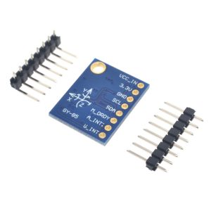
Pinout & Connection Guide
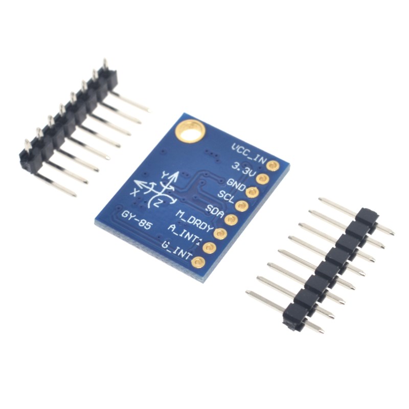
The GY-85 module features a 6-pin configuration for easy connection.
Pin Definitions
I2C Pin Mapping for Common Development Boards
Wiring Diagram (Arduino Uno)
GY-85 Module          →    Arduino Uno
─────────────────────────────────────────
VCC                   →    5V
GND                   →    GND
SCL                   →    A5 (SCL)
SDA                   →    A4 (SDA)
XDA (optional)        →    Leave unconnected
XCL (optional)        →    Leave unconnected
Important Notes:
-
The module includes built‑in logic level conversion, making it safe for direct connection to both 3.3V and 5V systems.
-
Most GY-85 modules include onboard pull-up resistors, but if you experience communication issues, you may need to add external 4.7kΩ pull-ups on SDA and SCL lines.
-
The XDA and XCL pins are auxiliary I2C connections used to daisy‑chain additional I2C sensors (e.g., a second accelerometer). For basic operation, leave them unconnected.
Sensor Details
ITG3205/ITG3200 – 3‑Axis Digital Gyroscope
The ITG3205 is a single‑chip MEMS gyroscope that measures angular velocity (rate of rotation) around the X, Y, and Z axes. Key features include:
-
16‑bit ADC for high‑resolution output
-
Fixed ±2000°/s measurement range
-
Programmable low‑pass filter for noise reduction
-
Built‑in temperature sensor for drift compensation
-
Low power: 6.5 mA active current, 5 µA standby
-
Fast I2C communication up to 400 kHz
Output scaling: The raw output of the ITG3205 is converted to degrees per second using the scale factor of 14.375 LSB per °/s.
ADXL345 – 3‑Axis Digital Accelerometer
The ADXL345 measures both static acceleration (gravity) for tilt sensing and dynamic acceleration from motion or shock. Key features include:
-
User‑selectable ranges: ±2g, ±4g, ±8g, or ±16g
-
10‑bit fixed resolution or 13‑bit full‑resolution mode (4 mg/LSB at ±16g)
-
Ultra‑low power: 23 µA in measurement mode, 0.1 µA in standby
-
Activity/inactivity monitoring and free‑fall detection
-
32‑level FIFO buffer to reduce host processor load
The ADXL345 is ideal for tilt measurement and orientation detection.
HMC5883L – 3‑Axis Digital Magnetometer
The HMC5883L measures the Earth’s magnetic field to determine absolute heading (compass direction). Key features include:
-
12‑bit ADC with 2 mG per LSB resolution
-
±8 Gauss measurement range
-
Heading accuracy of 1° to 2° (with proper calibration)
-
Sampling rate up to 160 Hz (6 ms measurement time)
-
Integrated degaussing straps for resetting the sensor
-
Built‑in self‑test capability
For accurate heading, the magnetometer must be calibrated to compensate for magnetic interference from nearby components (motors, wires, batteries). Additionally, tilt compensation using accelerometer data is required for heading accuracy when the sensor is not perfectly level.
Usage Guide
Software Setup (Arduino IDE)
The GY-85 module is supported by several Arduino libraries. The most comprehensive is Jeff Rowberg’s I2Cdevlib, which provides individual libraries for each sensor.
Step 1: Install Required Libraries
The I2Cdevlib collection includes:
Download the libraries from https://github.com/jrowberg/i2cdevlib or install via Library Manager if available.
Step 2: Initialize All Three Sensors
GY-85 9-Axis IMU – Complete Sensor Initialization
Reads all three sensors simultaneously
*/
#include <Wire.h>
#include "I2Cdev.h"
#include "ADXL345.h"
#include "ITG3200.h"
#include "HMC5883L.h"
ADXL345 accel;
ITG3200 gyro;
HMC5883L mag;
int16_t ax, ay, az;
int16_t gx, gy, gz;
int16_t mx, my, mz;
void setup() {
Serial.begin(115200);
Wire.begin();
accel.initialize();
Serial.print("Accelerometer: ");
Serial.println(accel.testConnection() ? "Connected" : "Failed");
gyro.initialize();
Serial.print("Gyroscope: ");
Serial.println(gyro.testConnection() ? "Connected" : "Failed");
mag.initialize();
Serial.print("Magnetometer: ");
Serial.println(mag.testConnection() ? "Connected" : "Failed");
Serial.println("GY-85 Ready");
}
void loop() {
accel.getAcceleration(&ax, &ay, &az);
gyro.getRotation(&gx, &gy, &gz);
mag.getHeading(&mx, &my, &mz);
Serial.print("Accel: ");
Serial.print(ax); Serial.print(", ");
Serial.print(ay); Serial.print(", ");
Serial.println(az);
Serial.print("Gyro: ");
Serial.print(gx); Serial.print(", ");
Serial.print(gy); Serial.print(", ");
Serial.println(gz);
Serial.print("Mag: ");
Serial.print(mx); Serial.print(", ");
Serial.print(my); Serial.print(", ");
Serial.println(mz);
Serial.println("-------------------");
delay(100);
}
Step 3: Convert Raw Gyroscope Data to Degrees per Second
The ITG3205 outputs raw values that must be scaled using the sensitivity factor:
float convertToDegreesPerSecond(int16_t rawValue) {
return rawValue / 14.375;
}
Step 4: Calculate Tilt‑Compensated Heading
For accurate heading, you must compensate for tilt using accelerometer data:
float calculateHeading(float magX, float magY, float magZ,
float accX, float accY, float accZ) {
float pitch = atan2(-accX, sqrt(accY * accY + accZ * accZ));
float roll = atan2(accY, accZ);
float magX_comp = magX * cos(pitch) + magZ * sin(pitch);
float magY_comp = magX * sin(roll) * sin(pitch)
+ magY * cos(roll)
- magZ * sin(roll) * cos(pitch);
float heading = atan2(magY_comp, magX_comp);
if (heading < 0) heading += 2 * PI;
return heading * 180 / PI;
}
Q: What is the advantage of a 9‑axis IMU over using a single sensor?
Each sensor has inherent limitations. Gyroscopes drift over time (integrating errors). Accelerometers cannot measure yaw (rotation around the vertical axis). Magnetometers are affected by magnetic interference. By combining data from all three sensors using a sensor fusion algorithm (e.g., Madgwick or Mahony filter), you obtain stable, accurate, drift‑free 3D orientation.
Q: What are the I2C addresses for the sensors on the GY-85 module?
-
ADXL345 (accelerometer): 0x53
-
ITG3205 (gyroscope): 0x68
-
HMC5883L (magnetometer): 0x1E
Q: Can I use the GY-85 with a 5V microcontroller like Arduino Uno?
Yes. The GY-85 includes a built‑in logic level converter (LLC circuit), making it compatible with both 3.3V and 5V systems. Connect VCC to 5V and SDA/SCL directly to the I2C pins.
Q: Can I use this module with an ESP32 or ESP8266?
Yes. Connect VCC to 3.3V and SDA/SCL to the appropriate I2C pins (GPIO21/22 for ESP32, GPIO4/5 for ESP8266). The module works well with both platforms.
Q: Why does my magnetometer reading not point to true north?
The HMC5883L measures magnetic north, not true north. The difference (magnetic declination) varies by geographic location. You must correct for declination in software using your local declination angle.
Q: What is the output range of the gyroscope (ITG3205)?
The ITG3205 has a fixed full‑scale range of ±2000 degrees per second. Raw values are converted using the sensitivity of 14.375 LSB per °/s.
Q: What oversampling settings should I use for the accelerometer?
The ADXL345 can be used in 10‑bit fixed resolution or 13‑bit full‑resolution mode. For most orientation applications, 13‑bit full‑resolution mode provides better sensitivity and is recommended.
Q: Do I need to calibrate the magnetometer?
Yes. The magnetometer is sensitive to magnetic interference from your circuit (motors, wires, batteries). Running a calibration routine (rotating the sensor in figure‑eight patterns) measures hard‑iron offsets and improves heading accuracy to 1°–2°.
Q: Can this module be used for head‑tracking in VR/FPV applications?
Yes. The GY-85 is widely used in DIY head‑tracking systems for FPV drones. The gyroscope provides fast angular response, while the accelerometer and magnetometer help correct drift.
Q: What is the power consumption of the GY-85 module?
Total consumption depends on the individual sensors:
-
ADXL345: 23 µA (measurement), 0.1 µA (standby)
-
ITG3205: 6.5 mA (active), 5 µA (standby)
-
HMC5883L: Very low (typically 100‑200 µA)
Total active current is approximately 7‑8 mA, making the module suitable for battery‑powered applications.