Product Overview
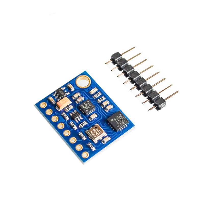
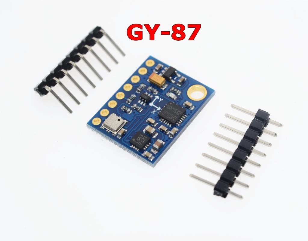
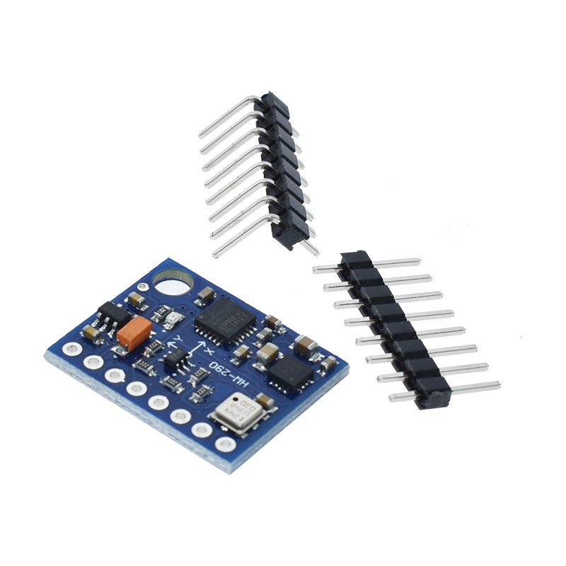
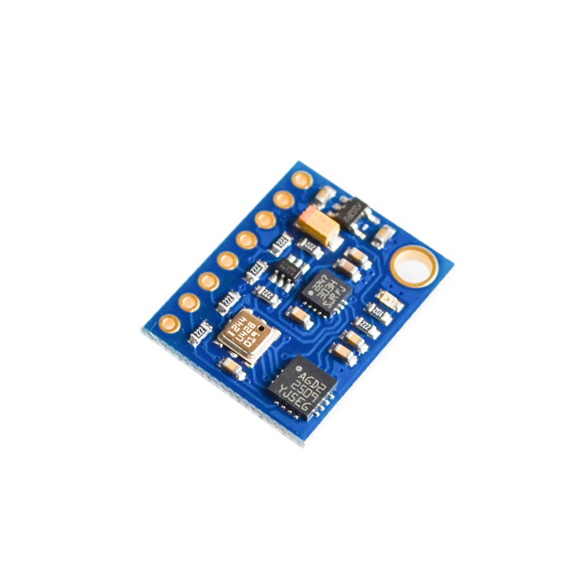
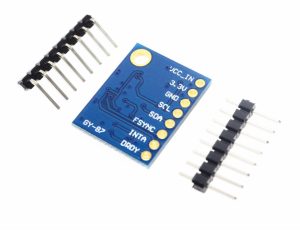
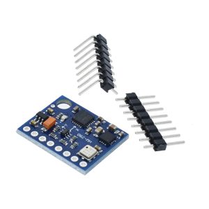
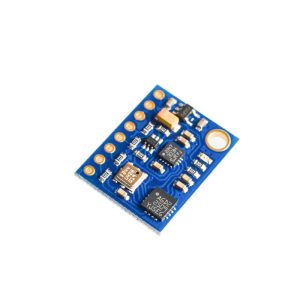
The GY-89 10DOF Sensor Module is a comprehensive motion-tracking board that integrates three high-performance sensors on a single compact PCB. This module combines a 3-axis gyroscope (L3GD20) , a 3-axis accelerometer and 3-axis magnetometer (LSM303D) , and a barometric pressure/temperature sensor (BMP180) , providing a complete 10-degree-of-freedom (10DOF) sensing solution for advanced motion and environmental monitoring applications .
The GY-89 is widely used in quadcopters, self-balancing robots, GPS navigation systems, head-tracking devices, and weather stations . All sensors communicate via a shared I2C bus, requiring only two data lines (SDA and SCL) to connect to your microcontroller. The module operates on 3V to 5V power and includes onboard logic-level conversion, making it directly compatible with both 3.3V and 5V systems such as Arduino, ESP32, ESP8266, Raspberry Pi, and STM32 .
Key Features
-
10 Degrees of Freedom (10DOF): Combines gyroscope (3 axes), accelerometer (3 axes), magnetometer (3 axes), and barometer (1 axis) on one board .
-
L3GD20 3‑Axis Gyroscope: Digital angular rate sensor with user‑selectable full scales of ±250, ±500, or ±2000 dps. Output is 16‑bit per axis .
-
LSM303D 6‑Axis Sensor: Integrates a 3‑axis accelerometer (selectable ±2/±4/±6/±8/±16g) and a 3‑axis magnetometer (selectable ±2/±4/±8/±12 gauss) on a single chip .
-
BMP180 Barometric Pressure/Temperature Sensor: High‑precision pressure sensor with 24‑bit output. Pressure range: 300–1100 hPa; altitude resolution: approximately 0.25m .
-
Single I2C Interface: All sensors share the same I2C bus, requiring only 2 pins (SDA, SCL) to communicate with all three sensors .
-
Wide Voltage Compatibility: Operating voltage range of 2.5V to 5.5V, compatible with both 3.3V and 5V microcontrollers .
-
Dual Communication Interfaces: Supports both I2C and SPI communication protocols (selected via chip select pins) .
-
Compact Form Factor: Dimensions of approximately 22mm × 17mm, ideal for drones and space‑constrained projects .
Technical Specifications
Pinout & Connection Guide
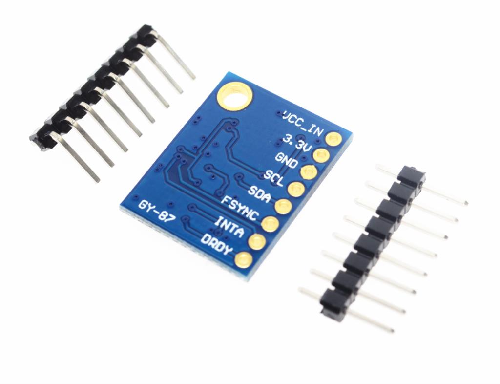
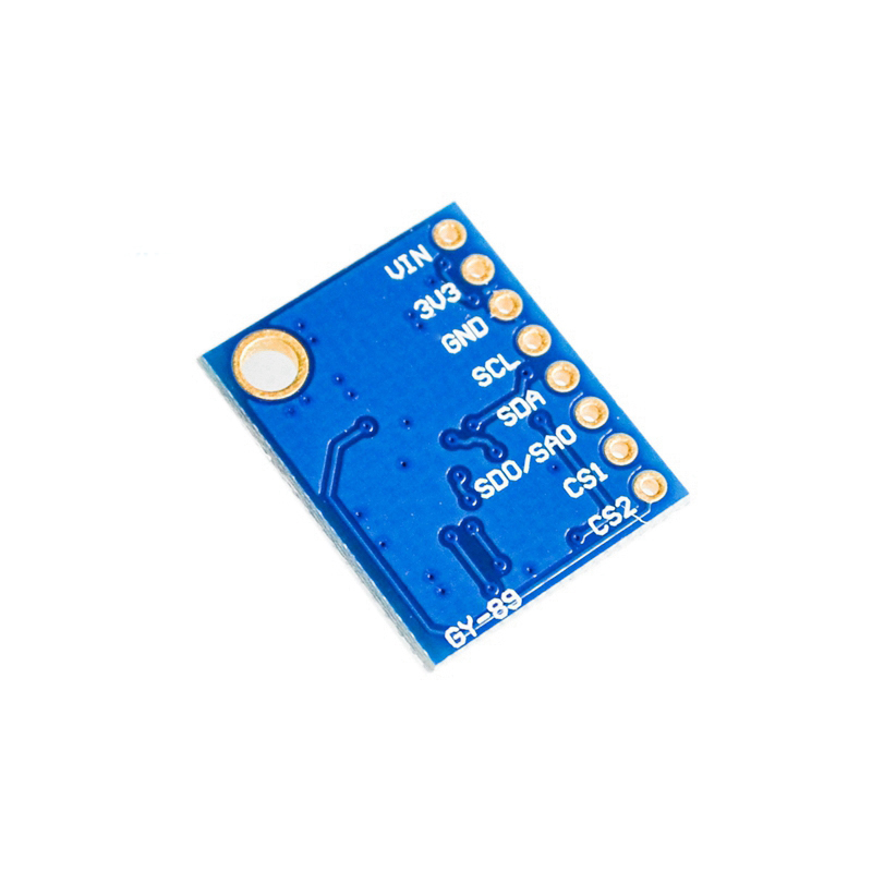
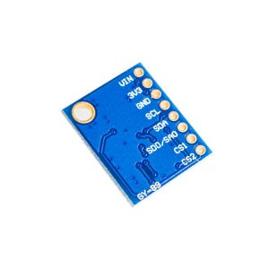
The GY-89 module uses a standard 6-pin or 8-pin configuration. Pin labeling may vary slightly between manufacturers; always verify the silkscreen on your specific board .
Wiring Diagram (I2C Mode – Recommended)
For basic operation, connect only the power and I2C pins:
Chip Select Pins (CS1/CS2): In I2C mode, these pins determine which sensor is active. The typical configuration is:
-
LSM303D active: Set CS1 = LOW, CS2 = HIGH
-
L3GD20 active: Set CS1 = HIGH, CS2 = LOW
-
BMP180 active: Uses CS1 = HIGH, CS2 = HIGH (default I2C without chip select)
Sensor Details
L3GD20 – 3‑Axis Digital Gyroscope
The L3GD20 measures angular velocity (rate of rotation) around the X, Y, and Z axes .
-
16‑bit ADC for high‑resolution output
-
User‑programmable ranges: ±250, ±500, or ±2000 dps
-
Programmable low‑pass filter for noise reduction
-
Low power consumption: 6.5 mA active current
LSM303D – 6‑Axis Accelerometer + Magnetometer
The LSM303D integrates a 3‑axis accelerometer and a 3‑axis magnetometer on a single chip .
-
Accelerometer ranges: ±2, ±4, ±6, ±8, or ±16 g (16‑bit output)
-
Magnetometer ranges: ±2, ±4, ±8, or ±12 gauss (16‑bit output)
-
Combined tilt‑compensated compass capability – accelerometer data can correct magnetometer readings for device tilt
BMP180 – Barometric Pressure & Temperature Sensor
The BMP180 measures atmospheric pressure and temperature .
-
24‑bit ADC for high‑precision pressure conversion
-
Pressure range: 300 – 1100 hPa (covers altitudes from -500m to +9000m)
-
Altitude resolution: Approximately 0.25m (0.17m in high‑resolution mode)
-
Factory‑calibrated coefficients stored in internal PROM – no user calibration required
Usage Guide
Software Setup (Arduino IDE)
Step 1: Install Required Libraries
The GY-89 uses three separate sensors, each with its own library:
Install via Arduino Library Manager: Sketch → Include Library → Manage Libraries.
Step 2: Chip Select Configuration for I2C Mode
Important: The GY-89 uses the CS1 and CS2 pins to select which sensor is active on the I2C bus . Before reading any sensor, you must set the appropriate CS pins:
#define CS1_PIN 8
#define CS2_PIN 9
void selectBMP180() {
digitalWrite(CS1_PIN, HIGH);
digitalWrite(CS2_PIN, HIGH);
}
void selectL3GD20() {
digitalWrite(CS1_PIN, HIGH);
digitalWrite(CS2_PIN, LOW);
}
void selectLSM303D() {
digitalWrite(CS1_PIN, LOW);
digitalWrite(CS2_PIN, HIGH);
}
Step 3: Basic Sensor Initialization
GY-89 10DOF Module – Complete Sensor Initialization Example
*/
#include <Wire.h>
#include <Adafruit_Sensor.h>
#include <Adafruit_BMP085.h>
#include <Adafruit_LSM303_Accel.h>
#include <Adafruit_LSM303_Mag.h>
#include <L3G.h>
#define CS1_PIN 8
#define CS2_PIN 9
Adafruit_BMP085 bmp;
Adafruit_LSM303_Accel_Unified accel = Adafruit_LSM303_Accel_Unified(12345);
Adafruit_LSM303_Mag_Unified mag = Adafruit_LSM303_Mag_Unified(12345);
L3G gyro;
void setup() {
Serial.begin(115200);
Wire.begin();
pinMode(CS1_PIN, OUTPUT);
pinMode(CS2_PIN, OUTPUT);
selectBMP180();
if (!bmp.begin()) {
Serial.println("BMP180 not found!");
} else {
Serial.println("BMP180 OK");
}
selectL3GD20();
if (!gyro.init()) {
Serial.println("L3GD20 not found!");
} else {
gyro.enableDefault();
Serial.println("L3GD20 OK");
}
selectLSM303D();
if (!accel.begin()) {
Serial.println("LSM303D Accelerometer not found!");
} else {
Serial.println("LSM303D Accelerometer OK");
}
if (!mag.begin()) {
Serial.println("LSM303D Magnetometer not found!");
} else {
Serial.println("LSM303D Magnetometer OK");
}
Serial.println("GY-89 All Sensors Ready");
}
void selectBMP180() {
digitalWrite(CS1_PIN, HIGH);
digitalWrite(CS2_PIN, HIGH);
}
void selectL3GD20() {
digitalWrite(CS1_PIN, HIGH);
digitalWrite(CS2_PIN, LOW);
}
void selectLSM303D() {
digitalWrite(CS1_PIN, LOW);
digitalWrite(CS2_PIN, HIGH);
}
Step 4: Reading Sensor Data
void loop() {
selectBMP180();
float temperature = bmp.readTemperature();
float pressure = bmp.readPressure() / 100.0;
float altitude = bmp.readAltitude();
selectL3GD20();
gyro.read();
float gx = gyro.g.x, gy = gyro.g.y, gz = gyro.g.z;
selectLSM303D();
sensors_event_t accelEvent;
accel.getEvent(&accelEvent);
sensors_event_t magEvent;
mag.getEvent(&magEvent);
float heading = atan2(magEvent.magnetic.y, magEvent.magnetic.x);
if(heading < 0) heading += 2 * PI;
heading = heading * 180 / PI;
Serial.print("Temp: "); Serial.print(temperature); Serial.println(" °C");
Serial.print("Pressure: "); Serial.print(pressure); Serial.println(" hPa");
Serial.print("Altitude: "); Serial.print(altitude); Serial.println(" m");
Serial.print("Gyro (°/s): "); Serial.print(gx); Serial.print(", "); Serial.print(gy); Serial.print(", "); Serial.println(gz);
Serial.print("Heading: "); Serial.println(heading);
delay(500);
}
Step 5: Calculating Tilt‑Compensated Heading
For accurate compass heading when the device is tilted, you must compensate using accelerometer data :
float calculateTiltCompensatedHeading(float accX, float accY, float accZ, float magX, float magY, float magZ) {
float pitch = atan2(-accX, sqrt(accY * accY + accZ * accZ));
float roll = atan2(accY, accZ);
float magX_comp = magX * cos(pitch) + magZ * sin(pitch);
float magY_comp = magX * sin(roll) * sin(pitch) + magY * cos(roll) - magZ * sin(roll) * cos(pitch);
float heading = atan2(magY_comp, magX_comp);
if(heading < 0) heading += 2 * PI;
return heading * 180 / PI;
}
Q: What does 10DOF mean on the GY-89?
10DOF stands for 10 Degrees of Freedom: 3 axes from the gyroscope (L3GD20) + 3 axes from the accelerometer (LSM303D) + 3 axes from the magnetometer (LSM303D) + 1 barometric pressure channel (BMP180) .
Q: How do I select which sensor to read on the GY-89?
The GY-89 uses the CS1 and CS2 pins to select the active sensor on the I2C bus :
-
BMP180: CS1=HIGH, CS2=HIGH
-
L3GD20: CS1=HIGH, CS2=LOW
-
LSM303D: CS1=LOW, CS2=HIGH
Q: Can I use the GY-89 with a 5V microcontroller like Arduino Uno?
Yes. The GY-89 operates on 2.5V to 5.5V and includes onboard logic‑level conversion (LLC), making it compatible with both 3.3V and 5V systems .
Q: What are the I2C addresses for the sensors?
The sensors are selected via chip select pins rather than separate I2C addresses. However, when accessed through the I2C bus, the devices respond at addresses:
Q: Why do I get "not found" errors when I only have one library installed?
The GY-89 uses three separate sensors requiring three separate libraries . You need to install libraries for BMP180, L3GD20, and LSM303D individually. Also, ensure the CS pins are correctly configured before initializing each sensor .
Q: Can I use this module with ESP32 or ESP8266?
Yes. Connect VCC to 3.3V and SDA/SCL to the appropriate I2C pins. The chip select pins can be connected to any available GPIO. The module works well with both platforms.
Q: How do I calibrate the magnetometer for accurate heading?
The magnetometer requires calibration to compensate for hard‑iron offsets from nearby magnetic interference (motors, wires, batteries). Perform a figure‑eight calibration routine or record min/max values on each axis while rotating the sensor and calculate the offsets .
Q: What is the altitude resolution of the BMP180?
The BMP180 has a pressure resolution of 0.06 hPa, which translates to an altitude resolution of approximately 0.25 meters (0.17m in high-resolution mode) .
Q: Can the GY-89 be used for drone flight control?
Yes. The GY-89 is designed for motion tracking and is suitable for quadcopter flight controllers and self-balancing robots . It provides gyroscope for stabilization, accelerometer for tilt sensing, magnetometer for heading reference, and barometer for altitude hold.
Q: What is the measurement range of the gyroscope (L3GD20)?
The L3GD20 gyroscope supports three user‑selectable full‑scale ranges: ±250, ±500, or ±2000 degrees per second . Select the range based on your application (higher range for faster rotation, lower range for higher sensitivity).