Product Overview
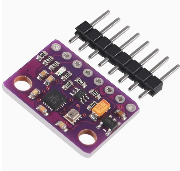
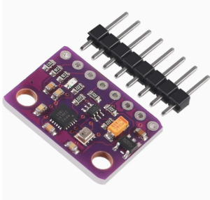
The GY-91 10DOF IMU Sensor Module is a high-precision motion tracking board that integrates a genuine MPU-9250 9-axis motion sensor with a BMP280 barometric pressure sensor on a single compact PCB. This powerful combination provides a complete 10-degree-of-freedom (10DOF) sensing solution, offering 3-axis accelerometer, 3-axis gyroscope, 3-axis magnetometer (compass), and barometric pressure/temperature readings in one tiny package.
Note: This is the original chip version with a fully functional magnetometer. The compass is verified working, making this module suitable for applications requiring absolute heading (yaw) tracking, unlike refurbished units where the magnetometer is often non-functional.
The MPU-9250 integrates a 3-axis gyroscope, 3-axis accelerometer, and a 3-axis magnetometer (AK8963) on a single silicon die. The BMP280 provides high-precision pressure and temperature readings for altitude estimation. This combination makes the GY-91 an ideal choice for drones, robotics, wearable devices, AHRS systems, and any project requiring accurate orientation and altitude tracking.
The module operates from 3V to 5V power (thanks to an onboard low-dropout regulator) and supports both I2C and SPI communication protocols, making it directly compatible with Arduino, ESP32, ESP8266, STM32, and Raspberry Pi.
Key Features
-
Complete 10-DOF Sensing: 3-axis accelerometer + 3-axis gyroscope + 3-axis magnetometer + barometric pressure sensor
-
Genuine MPU-9250 Chip: Features a fully functional AK8963 magnetometer for accurate compass heading (verified working)
-
BMP280 High-Precision Barometer: Measures atmospheric pressure (300-1100 hPa) for altitude estimation with high accuracy
-
Selectable Measurement Ranges:
-
Gyroscope: ±250, ±500, ±1000, ±2000 dps
-
Accelerometer: ±2g, ±4g, ±8g, ±16g
-
Magnetometer: ±4800 µT
-
Dual Communication Protocols: Supports both I2C and SPI interfaces for flexible microcontroller integration
-
16-bit ADC Resolution: High-resolution data output for precise motion tracking
-
Wide Operating Voltage: 3.0V – 5.0V DC with onboard low-dropout regulator, compatible with both 3.3V and 5V systems
-
Low Power Consumption: Ultra-low 6.2mA active current, ideal for battery-powered projects
-
Compact Size: Small footprint (14.3mm × 20.5mm) with 2.54mm pitch for easy breadboard integration
-
Wide Operating Temperature: -40°C to +85°C
Technical Specifications
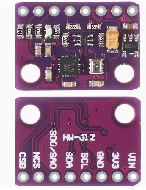
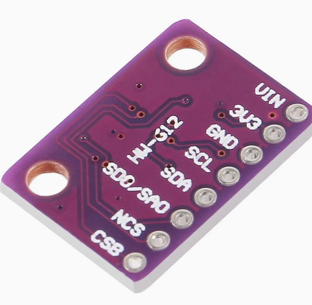
Pinout & Connection Guide
Pin Definitions
I2C Mode Wiring (Recommended – Uses 2 pins)
For I2C communication (simplest wiring), connect NCS and CSB to VCC (HIGH) to disable SPI mode.
I2C Address Configuration
SPI Mode Wiring (For higher data rates)
Usage Guide
Understanding the Sensors
The MPU-9250 is actually a multi-chip module (MCM) containing two separate dies:
The BMP280 is a separate chip providing barometric pressure and temperature readings. Together, they provide a complete 10-DOF sensing solution.
Software Setup (Arduino IDE)
Step 1: Install Required Libraries
Install the following libraries via Arduino Library Manager:
-
MPU9250 by bolderflight – Comprehensive library supporting both I2C and SPI
-
Adafruit BMP280 Library – For the barometer
-
Madgwick or Mahony – For sensor fusion (optional)
Step 2: I2C Address Verification
Before writing code, run this I2C scanner to verify all three sensors are detected:
#include <Wire.h>

void setup() {
  Wire.begin();
  Serial.begin(9600);
  Serial.println("I2C Scanner");
}

void loop() {
  byte error, address;
  int nDevices = 0;

  for(address = 1; address < 127; address++) {
    Wire.beginTransmission(address);
    error = Wire.endTransmission();

    if(error == 0) {
      Serial.print("I2C device found at address 0x");
      if(address < 16) Serial.print("0");
      Serial.println(address, HEX);
      nDevices++;
    }
  }

  if(nDevices == 0) Serial.println("No I2C devices found");
  delay(5000);
}
Expected output: Addresses 0x68 (MPU9250 gyro/accel), 0x0C (AK8963 magnetometer), and 0x76/0x77 (BMP280). The presence of address 0x0C confirms the magnetometer is functional.
Step 3: Basic Test Sketch (Full 10-DOF Read)
GY-91 Original Chip – Complete 10-DOF Read Example
Gyroscope + Accelerometer + Magnetometer + Barometer
*/
#include <Wire.h>
#include <MPU9250.h>
#include <Adafruit_BMP280.h>
MPU9250 mpu;
Adafruit_BMP280 bmp;
void setup() {
Serial.begin(115200);
Wire.begin();
if (!mpu.setup(0x68)) {
Serial.println("MPU9250 not found!");
while (1);
}
mpu.setGyroRange(2000);
mpu.setAccelRange(16);
if (!bmp.begin(0x76)) {
Serial.println("BMP280 not found!");
while (1);
}
Serial.println("GY-91 Original Chip Ready (Full 10-DOF)");
Serial.println("-----------------------------------------");
}
void loop() {
if (mpu.update()) {
float ax = mpu.getAccX();
float ay = mpu.getAccY();
float az = mpu.getAccZ();
float gx = mpu.getGyroX();
float gy = mpu.getGyroY();
float gz = mpu.getGyroZ();
float mx = mpu.getMagX();
float my = mpu.getMagY();
float mz = mpu.getMagZ();
float heading = atan2(my, mx) * 180 / PI;
if (heading < 0) heading += 360;
float temperature = bmp.readTemperature();
float pressure = bmp.readPressure();
float altitude = bmp.readAltitude(1013.25);
float pitch = atan2(-ax, sqrt(ay * ay + az * az)) * 180 / PI;
float roll = atan2(ay, az) * 180 / PI;
Serial.print("Accel (g): ");
Serial.print(ax); Serial.print(", ");
Serial.print(ay); Serial.print(", ");
Serial.println(az);
Serial.print("Gyro (°/s): ");
Serial.print(gx); Serial.print(", ");
Serial.print(gy); Serial.print(", ");
Serial.println(gz);
Serial.print("Mag (µT): ");
Serial.print(mx); Serial.print(", ");
Serial.print(my); Serial.print(", ");
Serial.println(mz);
Serial.print("Heading: ");
Serial.print(heading);
Serial.println("°");
Serial.print("Pitch: ");
Serial.print(pitch);
Serial.print("°, Roll: ");
Serial.println(roll);
Serial.print("Temp: ");
Serial.print(temperature);
Serial.println(" °C");
Serial.print("Pressure: ");
Serial.print(pressure / 100.0);
Serial.println(" hPa");
Serial.print("Altitude: ");
Serial.print(altitude);
Serial.println(" m");
Serial.println("-----------------------------------------");
}
delay(100);
}
Step 4: Enabling AHRS (Attitude and Heading Reference System)
For true 3D orientation (yaw, pitch, roll), you can use a sensor fusion library like Madgwick or Mahony. These algorithms combine gyroscope, accelerometer, and magnetometer data to produce drift-free orientation angles.
#include <MadgwickAHRS.h>
Madgwick filter;
float roll, pitch, yaw;
void setup() {
filter.begin(100);
}
void loop() {
if (mpu.update()) {
filter.update(gx * PI/180, gy * PI/180, gz * PI/180,
ax, ay, az,
mx, my, mz);
roll = filter.getRoll();
pitch = filter.getPitch();
yaw = filter.getYaw();
Serial.print("Yaw: ");
Serial.print(yaw);
Serial.print("°, Pitch: ");
Serial.print(pitch);
Serial.print("°, Roll: ");
Serial.println(roll);
}
}
Magnetometer Calibration for Accurate Heading
For accurate compass heading, the magnetometer must be calibrated to compensate for hard-iron and soft-iron distortions caused by nearby magnetic materials (motors, wires, batteries).
Simple Hard-Iron Calibration Procedure:
-
Connect the module to your microcontroller and run the MPU9250 library’s magnetometer calibration example
-
Rotate the sensor in a figure-eight pattern for about 30 seconds
-
The library will collect min/max values for each axis
-
Save the calibration offsets and apply them to future readings
Applications
The GY-91 is ideal for:
-
Drone Flight Control Systems: Stabilization, orientation, and altitude tracking
-
Robotics Navigation: IMU fusion and dead reckoning
-
Wearable Devices: Motion tracking and activity monitoring
-
AR/VR Systems: Orientation sensing and motion interaction
-
GPS Enhancement: Compass and altitude correction
-
AHRS Systems: Attitude and Heading Reference Systems
-
Indoor Navigation: Orientation and altitude for positioning
Q: Is the magnetometer on this module functional?
Yes. This is the original chip version with a fully functional AK8963 magnetometer. Verified working, it provides accurate compass heading measurements. The magnetometer I2C address 0x0C will respond when scanned.
Q: What is the difference between this module and refurbished GY-91 modules?
Refurbished GY-91 modules often have a non-functional magnetometer (the AK8963 chip defective or missing). This original chip version has a fully functional magnetometer, providing complete 9-axis motion tracking including absolute heading (yaw).
Q: What is the difference between MPU9250 and MPU9255?
The MPU9250 and MPU9255 are very similar; both contain the same AK8963 magnetometer and MPU-6515 gyro/accel. The primary difference is in the register map; software written for one may work with minor modifications.
Q: What are the I2C addresses of the sensors?
The presence of address 0x0C confirms the magnetometer is functional.
Q: Can I use this module with a 5V Arduino Uno?
Yes. The module includes an onboard voltage regulator that accepts 3V–5V input. Connect VIN to 5V and SDA/SCL directly to the I2C pins.
Q: Can I use this module with ESP32 or ESP8266?
Yes. Connect VIN to 3.3V and SDA/SCL to the appropriate I2C pins (GPIO21/22 for ESP32, GPIO4/5 for ESP8266). The same libraries work on these platforms.
Q: What is the BMP280 pressure range and altitude resolution?
The BMP280 measures pressure from 300 to 1100 hPa, corresponding to altitudes from approximately -500 meters to +9,000 meters. The altitude resolution can be as fine as 0.1 meters with proper calibration.
Q: Do I need to calibrate the sensors?
The gyroscope and accelerometer are factory-calibrated but benefit from a simple offset calibration. The magnetometer requires calibration for accurate heading measurements due to hard-iron distortions from nearby magnetic materials. Most MPU9250 libraries include calibration functions.
Q: What is the power consumption of this module?
The module draws approximately 6.2 mA in active mode, making it suitable for battery-powered applications. The BMP280 consumes additional power, so total consumption is slightly higher.
Q: Can I use this module with Raspberry Pi?
Yes. Enable I2C via raspi-config, connect VIN to 3.3V (Pin 1), GND to GND, SCL to GPIO3 (Pin 5), and SDA to GPIO2 (Pin 3). Use Python libraries such as adafruit-circuitpython-mpu9250 or mpu9250-python.