GY-9250 9-Axis Motion Tracking Sensor Module (I2C/SPI, with Magnetometer) – Original Chip

SKU: FA2168-1
Sensor Chip

Original InvenSense MPU-9250

Operating Voltage (VCC)

3V – 5V DC

Communication Protocols

I2C, SPI

Default I2C Address

0x68 (7-bit)

Gyroscope Ranges

±250, ±500, ±1000, ±2000 dps

Accelerometer Ranges

±2g, ±4g, ±8g, ±16g

Magnetometer Range

±4800 µT

ADC Resolution

16-bit

Digital Motion Processor (DMP)

Yes

FIFO Buffer Size

512 bytes

I2C Bus Speed (Max)

400 kHz

Operating Temperature

-40°C to +85°C

Module Dimensions

15mm × 25mm

Pin Spacing

2.54mm

Product Overview

The GY-9250 9-Axis Motion Tracking Sensor Module is a high-performance inertial measurement unit (IMU) based on the original InvenSense MPU-9250 chip. This compact module combines a 3-axis gyroscope, a 3-axis accelerometer, and a 3-axis magnetometer in a single package, providing complete 9-degree-of-freedom (9-DOF) motion tracking for your embedded projects .

The MPU-9250 is a multi-chip module (MCM) consisting of two dies integrated into a single QFN package: one die houses the 3-axis gyroscope and 3-axis accelerometer, while the other houses the AK8963 3-axis magnetometer . This integration, combined with an onboard Digital Motion Processor (DMP), allows the MPU-9250 to perform complex 9-axis MotionFusion algorithms directly on the chip, reducing the processing load on your main microcontroller .

Communication with the module is flexible, supporting both I2C and SPI interfaces. The module includes an onboard 3.3V voltage regulator and pull-up resistors, making it directly compatible with both 3.3V and 5V systems like Arduino, ESP32, ESP8266, Raspberry Pi, and STM32 .

Whether you are building a drone flight controller, a self-balancing robot, a VR headset, an AHRS system, or any application requiring precise orientation tracking, this original GY-9250 module delivers the accuracy and reliability you need.

Key Features

  • Complete 9-Axis Motion Tracking: Combines 3-axis gyroscope, 3-axis accelerometer, and 3-axis magnetometer for full 3D orientation sensing .

  • Digital Motion Processor (DMP): Onboard processor can perform complex 9-axis MotionFusion algorithms, offloading sensor fusion tasks from your main microcontroller .

  • 16-bit ADC Output: High-resolution 16-bit analog-to-digital converters for each sensor provide precise, high-fidelity motion data .

  • Selectable Measurement Ranges:

    • Gyroscope: ±250, ±500, ±1000, ±2000°/s (degrees per second) 

    • Accelerometer: ±2g, ±4g, ±8g, ±16g 

    • Magnetometer: ±4800µT (microtesla) 

  • Dual Communication Interfaces: Supports both I2C (up to 400 kHz) and SPI protocols for flexible microcontroller integration .

  • Onboard 3.3V Regulator & Level Shifter: Accepts 3V–5V power input and includes logic level conversion, making it directly compatible with both 3.3V and 5V systems .

  • Built-in Pull-up/Pull-down Resistors: Includes pull-up resistors on SDA, SCL, and nCS lines, and pull-down resistors on FSYNC and AD0 lines for simplified wiring .

  • 512-Byte FIFO Buffer: On-chip FIFO allows data to be stored and retrieved in bursts, reducing host processor intervention and enabling low-power applications .

  • Embedded Temperature Sensor: On-chip temperature sensor for drift compensation and system monitoring .

  • Compact Form Factor: Small PCB size (approx. 15mm × 25mm) with 2.54mm pin spacing fits easily into space-constrained projects .

  • Immersion Gold PCB: High-quality PCB with gold-plated pads for better solderability and corrosion resistance .

Technical Specifications

Parameter Operating Value
Sensor Chip Original InvenSense MPU-9250 
Operating Voltage (VCC) 3V – 5V DC 
Communication Protocols I2C, SPI 
Default I2C Address 0x68 (7-bit) 
Gyroscope Ranges ±250, ±500, ±1000, ±2000 dps 
Accelerometer Ranges ±2g, ±4g, ±8g, ±16g 
Magnetometer Range ±4800 µT 
ADC Resolution 16-bit 
Digital Motion Processor (DMP) Yes 
FIFO Buffer Size 512 bytes 
I2C Bus Speed (Max) 400 kHz 
Operating Temperature -40°C to +85°C 
Module Dimensions 15mm × 25mm 
Pin Spacing 2.54mm 

Pinout & Connection Guide

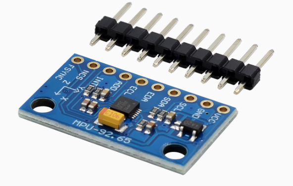
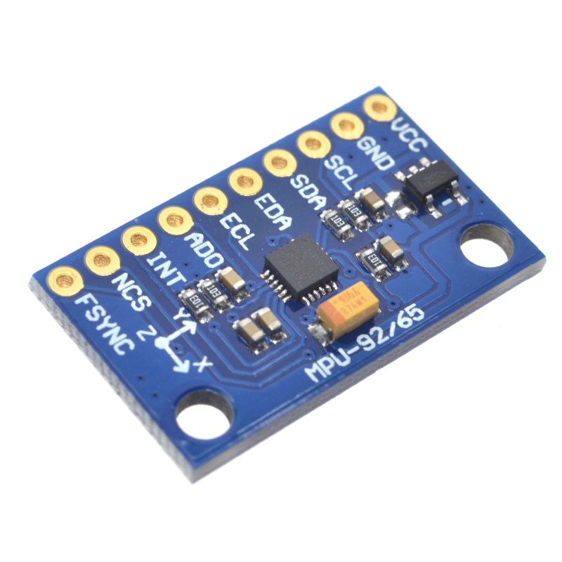
The GY-9250 module features a 10-pin configuration (2.54mm pitch). Pin labels may vary slightly between manufacturers; always verify the silkscreen on your specific board .

Pin Definitions

Pin Label Function Description
1 VCC Power Supply Connect to 3.3V or 5V DC power source
2 GND Ground Common ground connection
3 SCL/SCLK I2C Clock / SPI Clock Connect to SCL (I2C) or SCK (SPI)
4 SDA/SDI I2C Data / SPI Data In Connect to SDA (I2C) or MOSI (SPI)
5 nCS SPI Chip Select Active low; connect to CS pin in SPI mode
6 AD0/SDO I2C Address / SPI Data Out I2C: selects address; SPI: MISO output
7 FSYNC Frame Sync Optional; can be left unconnected
8-10 Additional Pins Refer to specific module documentation

Interface Mode Selection

Mode nCS AD0/SDO Pins Used
I2C VCC (HIGH) GND = 0x68, VCC = 0x69 SCL, SDA
SPI MCU GPIO (LOW to select) SDO (MISO) SCLK, SDI, SDO, nCS

I2C Address Configuration

The I2C address is controlled by the AD0 pin :

AD0 Pin Connection I2C Address (7-bit)
Connected to GND 0x68 (default)
Connected to VCC 0x69

Wiring Diagrams

I2C Mode (Recommended – Uses 2 pins):

GY-9250 Pin Arduino Uno ESP32 ESP8266 Raspberry Pi
VCC 5V 3.3V 3.3V 3.3V (Pin 1)
GND GND GND GND GND (Pin 6)
SCL A5 (SCL) GPIO22 GPIO5 (D1) GPIO3 (Pin 5)
SDA A4 (SDA) GPIO21 GPIO4 (D2) GPIO2 (Pin 3)
AD0 GND GND GND GND

SPI Mode (For higher data rates):

GY-9250 Pin Arduino Uno ESP32
VCC 5V 3.3V
GND GND GND
SCL D13 (SCK) GPIO18
SDA D11 (MOSI) GPIO23
nCS D10 GPIO5
AD0 (SDO) D12 (MISO) GPIO19

Note: The module is designed to be powered from 5V sources such as an Arduino. If you desire to power the module from 3.3V, you can bridge the solder jumper next to the voltage regulator to bypass the regulator .

Theory of Operation

How the MPU-9250 Works

The MPU-9250 integrates three MEMS (Micro-Electro-Mechanical Systems) sensors in a single package :

  • Gyroscope: Measures angular velocity (rate of rotation) around the X, Y, and Z axes using vibrating MEMS structures that respond to Coriolis forces.

  • Accelerometer: Measures linear acceleration (including gravity) using capacitive sensing elements that deflect under acceleration.

  • Magnetometer: Measures the Earth’s magnetic field using Hall-effect sensors with a magnetic concentrator, providing absolute heading reference .

The sensor outputs are digitized by 16-bit ADCs and can be read via I2C or SPI. The DMP (Digital Motion Processor) can perform sensor fusion to combine data from all three sensors, providing stable, drift-free 3D orientation (yaw, pitch, roll) without complex calculations on your main microcontroller .

Sensor Fusion Importance

Using a single sensor has limitations:

  • Gyroscope: Measures rate of rotation; integrating to get angle leads to drift over time.

  • Accelerometer: Cannot measure yaw (rotation around vertical axis) and is affected by linear acceleration.

  • Magnetometer: Provides absolute heading reference but is susceptible to magnetic interference.

Sensor fusion combines data from all three sensors to produce accurate, stable orientation. The DMP handles this fusion onboard, outputting quaternion or Euler angles directly.

Converting Raw Data to Physical Units

Gyroscope (Angular Velocity)

Raw gyroscope values must be divided by the sensitivity for the selected range:

Range Sensitivity (LSB per °/s)
±250°/s 131
±500°/s 65.5
±1000°/s 32.8
±2000°/s 16.4

Example: For ±2000°/s range, angular_rate (°/s) = raw_value / 16.4.

Accelerometer (Acceleration)

Raw accelerometer values must be divided by the sensitivity for the selected range:

Range Sensitivity (LSB per g)
±2g 16384
±4g 8192
±8g 4096
±16g 2048

Example: For ±2g range, acceleration (g) = raw_value / 16384.

Magnetometer (Magnetic Field)

Raw magnetometer values are converted to microtesla (µT) or Gauss:

  • Sensitivity: 0.6 µT per LSB 

  • Alternatively, the range is ±4800 µT 

Examplemagnetic_field (µT) = raw_value × 0.6.

Usage Guide

Software Setup (Arduino IDE)

Step 1: Install Required Libraries

Several libraries support the MPU-9250. The most popular options include:

  • MPU9250 by hideakitai – Comprehensive, supports both I2C and SPI 

  • MPU9250 by bolderflight – Well-documented, supports DMP features

  • mpu9250 by Electronic Cats – Simple and easy to use

Install via Arduino Library Manager:

  1. Open Arduino IDE → Sketch → Include Library → Manage Libraries

  2. Search for “MPU9250”

  3. Install your preferred library

Step 2: I2C Address Verification

Before writing code, verify your sensor’s I2C address using this scanner:

cpp
#include <Wire.h>

void setup() {
  Wire.begin();
  Serial.begin(9600);
  Serial.println("I2C Scanner");
}

void loop() {
  byte error, address;
  int nDevices = 0;
  
  for(address = 1; address < 127; address++) {
    Wire.beginTransmission(address);
    error = Wire.endTransmission();
    
    if(error == 0) {
      Serial.print("I2C device found at address 0x");
      if(address < 16) Serial.print("0");
      Serial.println(address, HEX);
      nDevices++;
    }
  }
  
  if(nDevices == 0) Serial.println("No I2C devices found");
  delay(5000);
}

Expected output: Address 0x68 (or 0x69 if AD0 is pulled HIGH).

Step 3: Basic Test Sketch (Full 9-Axis Reading)

cpp
/*
  GY-9250 MPU-9250 Complete 9-Axis Read Example
  Reads gyroscope, accelerometer, and magnetometer data
*/

#include <Wire.h>
#include <MPU9250.h>

MPU9250 mpu;

void setup() {
  Serial.begin(115200);
  Wire.begin();
  delay(100);
  
  // Initialize MPU-9250 with I2C address 0x68
  if (!mpu.setup(0x68)) {
    Serial.println("MPU-9250 sensor not found! Check wiring.");
    while (1);
  }
  
  // Configure gyroscope range (±250, ±500, ±1000, ±2000 dps)
  mpu.setGyroRange(2000);
  
  // Configure accelerometer range (±2, ±4, ±8, ±16g)
  mpu.setAccelRange(16);
  
  Serial.println("GY-9250 MPU-9250 Ready (Full 9-Axis)");
  Serial.println("---------------------------------------");
}

void loop() {
  // Read all sensor data
  if (mpu.update()) {
    // Accelerometer data (in g-force)
    float ax = mpu.getAccX();
    float ay = mpu.getAccY();
    float az = mpu.getAccZ();
    
    // Gyroscope data (in degrees per second)
    float gx = mpu.getGyroX();
    float gy = mpu.getGyroY();
    float gz = mpu.getGyroZ();
    
    // Magnetometer data (in microtesla)
    float mx = mpu.getMagX();
    float my = mpu.getMagY();
    float mz = mpu.getMagZ();
    
    // Temperature
    float temp = mpu.getTemperature();
    
    // Calculate heading from magnetometer (magnetic north)
    float heading = atan2(my, mx) * 180 / PI;
    if (heading < 0) heading += 360;
    
    // Calculate tilt angles (pitch and roll) from accelerometer
    float pitch = atan2(-ax, sqrt(ay * ay + az * az)) * 180 / PI;
    float roll = atan2(ay, az) * 180 / PI;
    
    // Display results
    Serial.print("Accel (g): ");
    Serial.print(ax); Serial.print(", ");
    Serial.print(ay); Serial.print(", ");
    Serial.println(az);
    
    Serial.print("Gyro (°/s): ");
    Serial.print(gx); Serial.print(", ");
    Serial.print(gy); Serial.print(", ");
    Serial.println(gz);
    
    Serial.print("Mag (µT): ");
    Serial.print(mx); Serial.print(", ");
    Serial.print(my); Serial.print(", ");
    Serial.println(mz);
    
    Serial.print("Heading: ");
    Serial.print(heading);
    Serial.print("°, Pitch: ");
    Serial.print(pitch);
    Serial.print("°, Roll: ");
    Serial.println(roll);
    
    Serial.print("Temperature: ");
    Serial.print(temp);
    Serial.println(" °C");
    
    Serial.println("---------------------------------------");
  }
  
  delay(100);
}

Step 4: Using the Digital Motion Processor (DMP)

The DMP can perform sensor fusion to provide quaternion (3D orientation) output:

cpp
/*
  MPU-9250 DMP Example – Full 9-Axis Sensor Fusion
*/

#include <Wire.h>
#include <MPU9250_WE.h>

MPU9250_WE mpu = MPU9250_WE(&Wire);

void setup() {
  Serial.begin(115200);
  Wire.begin();
  
  if (!mpu.init()) {
    Serial.println("MPU9250 does not respond!");
    while (1);
  }
  
  // Enable DMP (Digital Motion Processor)
  if (!mpu.enableDMP()) {
    Serial.println("DMP could not be enabled!");
    while (1);
  }
  
  Serial.println("DMP ready – Outputting orientation angles");
}

void loop() {
  if (mpu.checkNewData()) {
    xyzFloat angles = mpu.getAngles();
    
    Serial.print("Yaw: ");
    Serial.print(angles.x);
    Serial.print("°, Pitch: ");
    Serial.print(angles.y);
    Serial.print("°, Roll: ");
    Serial.println(angles.z);
  }
  
  delay(50);
}

Calibration for Accurate Orientation

For accurate heading and orientation, calibration is essential .

Gyroscope and Accelerometer Calibration

Place the sensor stationary on a level surface. The following calibration procedure is commonly used:

cpp
// Calibration function (from MPU9250 library examples)
mpu.calibrateAccelGyro();

During calibration, the sensor should not be moved. This measures the zero-g offsets and bias errors .

Magnetometer Calibration

Magnetometer calibration compensates for hard-iron and soft-iron distortions caused by nearby magnetic materials (motors, wires, batteries). The typical procedure involves moving the sensor in a figure-eight pattern while the library collects min/max values:

cpp
// Magnetometer calibration (from MPU9250 library examples)
Serial.println("Wave the device in a figure eight until it is finished");
mpu.calibrateMag();

After calibration, the calibration parameters can be saved and applied to future readings .

Calibration Parameters Output

After running calibration, you can retrieve the calibration parameters:

cpp
void print_calibration() {
  Serial.println("Accel bias [g]:");
  Serial.print(mpu.getAccBiasX() * 1000.f / (float)MPU9250::CALIB_ACCEL_SENSITIVITY);
  Serial.print(",");
  Serial.print(mpu.getAccBiasY() * 1000.f / (float)MPU9250::CALIB_ACCEL_SENSITIVITY);
  Serial.print(",");
  Serial.println(mpu.getAccBiasZ() * 1000.f / (float)MPU9250::CALIB_ACCEL_SENSITIVITY);
  
  Serial.println("Gyro bias [deg/s]:");
  Serial.print(mpu.getGyroBiasX() / (float)MPU9250::CALIB_GYRO_SENSITIVITY);
  Serial.print(",");
  Serial.print(mpu.getGyroBiasY() / (float)MPU9250::CALIB_GYRO_SENSITIVITY);
  Serial.print(",");
  Serial.println(mpu.getGyroBiasZ() / (float)MPU9250::CALIB_GYRO_SENSITIVITY);
  
  Serial.println("Mag bias [mG]:");
  Serial.print(mpu.getMagBiasX());
  Serial.print(",");
  Serial.print(mpu.getMagBiasY());
  Serial.print(",");
  Serial.println(mpu.getMagBiasZ());
}

Using the FIFO Buffer

The 512-byte FIFO buffer allows the sensor to store data samples, reducing host processor intervention. This is useful for low-power applications .

cpp
// Enable FIFO (example)
mpu.enableFIFO();
mpu.setFIFOEnabled(true);
Q: What is the difference between the GY-9250 and the MPU-9250?

The MPU-9250 is the actual sensor chip manufactured by InvenSense. The GY-9250 is the breakout module that contains the MPU-9250 chip along with supporting components (voltage regulator, pull-up resistors, etc.) for easy integration into projects .

Q: Does this module have a fully functional magnetometer?

Yes. Unlike refurbished or counterfeit modules, this original GY-9250 includes a fully functional AK8963 3-axis magnetometer, providing complete 9-axis motion tracking capability .

Q: What is the default I2C address of the GY-9250?

The default 7-bit I2C address is 0x68 when the AD0 pin is connected to GND. When AD0 is connected to VCC, the address becomes 0x69 .

Q: Can I use this module with a 5V microcontroller like Arduino Uno?

Yes. The module includes an onboard 3.3V voltage regulator and logic level converters, making it directly compatible with both 3.3V and 5V systems. Connect VCC to 5V and SDA/SCL directly to the I2C pins .

Q: Can I use this module with ESP32 or ESP8266?

Yes. Connect VCC to 3.3V and SDA/SCL to the appropriate I2C pins (GPIO21/22 for ESP32, GPIO4/5 for ESP8266). The same Arduino libraries work on these platforms .

Q: What is the Digital Motion Processor (DMP) and why is it useful?

The DMP is an onboard processor that can perform sensor fusion (combining gyroscope, accelerometer, and magnetometer data) to calculate orientation without burdening your main microcontroller. This frees up your MCU for other tasks and ensures consistent timing for motion processing .

Q: How do I calibrate the magnetometer for accurate heading?

Use the mpu.calibrateMag() function while moving the sensor in a figure-eight pattern. This collects min/max values and calculates hard-iron offsets. Calibration is essential for accurate compass heading .

Q: What are the measurement ranges of the gyroscope and accelerometer?

Gyroscope ranges: ±250, ±500, ±1000, ±2000°/s. Accelerometer ranges: ±2g, ±4g, ±8g, ±16g. These are user-selectable via library functions .

Q: What is the purpose of the FIFO buffer?

The 512-byte FIFO buffer stores sensor data samples, allowing the host processor to read data in bursts rather than continuously. This reduces power consumption and is especially useful in battery-powered applications .

Q: Can I use the GY-9250 with Raspberry Pi?

Yes. The module uses I2C, which is supported on Raspberry Pi. Enable I2C via raspi-config, connect VCC to 3.3V (Pin 1), GND to GND, SCL to GPIO3 (Pin 5), and SDA to GPIO2 (Pin 3). Use Python libraries such as adafruit-circuitpython-mpu9250 or mpu9250-python.