Description
The HC-12 V3.0 433MHz Long-Range Wireless Serial Module is a high-performance, long-range transceiver that offers an exceptional alternative to Bluetooth for projects requiring distance and reliability. Built around the high-performance SI4463 (or SI4438) RF chip, this module provides a robust wireless serial link of up to 1000 meters in open areas with proper antenna placement, making it ideal for applications where Wi-Fi and standard Bluetooth fall short .
Unlike simple RF modules that require complex low-level programming, the HC-12 acts as a transparent wireless serial cable. It features a built-in MCU that handles all RF protocol processing automatically, effectively functioning as a wireless replacement for a physical UART cable . Data sent into the module’s UART port is transmitted wirelessly and appears instantly at the UART port of another HC-12 module on the same channel, with no RF programming required by your microcontroller.
The module offers exceptional flexibility with 100 selectable channels in the 433.4–473.0 MHz band and multiple operating modes that allow you to balance power consumption against communication distance . Whether you need ultra-low power operation for battery-powered sensors or maximum range for remote control applications, the HC-12 can be configured to meet your needs using simple AT commands.
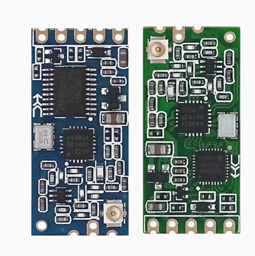
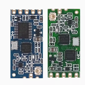
Hardware & Chipset Updates: The HC-12 V3.0 represents the latest hardware revision. While initial versions utilized the SI4463 transceiver IC, newer production batches feature the functionally equivalent SI4438 chip paired with an N32S032 (ARM Cortex-M0) microcontroller for enhanced processing capability . Both versions deliver the same high performance, with a notable improvement in signal sensitivity and reduced interference over earlier revisions.
The module is remarkably easy to use. It connects directly to any microcontroller via its UART pins (TX/RX), supports both 3.3V and 5V logic levels, and features a straightforward pinout . The green V3.0 PCB maintains the same pinout as previous versions, ensuring backward compatibility with existing designs while offering better performance .
Important Note: The module requires an external antenna (typically a spring or 17-23cm wire) to achieve maximum range. Soldering the included spring antenna to the ANT pad is recommended. The HC-12 is not compatible with the HC-11 module; all devices in your network must be HC-12 modules for successful communication .
Whether you need to build a remote weather station, control a device across a farm, create a wireless serial link between buildings, or replace wired connections with a reliable long-range alternative, the HC-12 V3.0 delivers exceptional performance in a compact, easy-to-use package.
Key Features
-
1000m Long Range – Up to 1 kilometer communication distance in open areas (at 5000bps air baud rate)
-
100 Selectable Channels – 433.4–473.0 MHz frequency range with 400KHz channel spacing
-
Transparent Serial Transmission – Built-in MCU handles all RF protocols; works like a wireless serial cable; no additional libraries required for basic operation
-
Adjustable Transmit Power – 8 power levels from -1dBm to +20dBm (100mW max)
-
Multiple Operating Modes – FU1 (3.6mA idle), FU2 (80µA idle), FU3 (16mA idle), FU4 (long-range) for power/performance optimization
-
Wide Voltage Range – 3.2V–5.5V DC, compatible with both 3.3V and 5V microcontrollers
-
Configurable via AT Commands – Set channel, baud rate, power level, and operating mode using simple text commands
-
High Receiver Sensitivity – -117dBm sensitivity ensures reliable reception even in challenging conditions
-
Wide Baud Rate Support – UART speeds from 1200 bps to 115200 bps (default: 9600 bps)
-
Industrial Temperature Range – -40°C to +85°C for reliable operation in harsh environments
Technical Parameters
Usage Guide
Hardware Overview
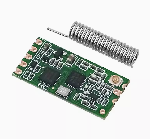
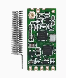
The HC-12 V3.0 module features a compact green PCB design with the RF chip (SI4463 or SI4438) and an onboard MCU. The module includes a spring antenna (included) and a SET pin for entering configuration mode .
Key Components:
-
SI4463/SI4438 RF Chip – High-performance FSK/GFSK transceiver
-
Onboard MCU (8051 or N32S032 ARM Cortex-M0) – Handles UART communication and AT command processing
-
Spring Antenna – Included for optimal range; must be soldered to the ANT pad
-
SET Pin – Used to enter AT command mode for configuration
Pinout Description
Wiring Instructions
Basic Connection (Microcontroller to HC-12):
Important Connection Notes:
-
When connecting two HC-12 modules to communicate with each other, you do not need to cross the TXD/RXD connections between modules. Simply connect each module’s TXD to its own microcontroller’s RX pin, and RXD to its TX pin .
-
The SET pin is internally pulled high. Leave it floating (disconnected) for normal operation. Pull it LOW (connect to GND) to enter AT command mode .
Antenna Connection:
-
The module includes a spring antenna that should be soldered to the ANT pad for optimal performance .
-
For maximum range, ensure the antenna is straight, vertical, and away from metal surfaces.
-
A simple 17-23cm straight copper wire can also be used as an antenna .
Operating Modes (FU1-FU4)
The HC-12 offers four operating modes that allow you to optimize for power consumption or performance :
Mode Characteristics:
-
FU1: Supports 8 serial baud rates (1200-115200bps). Idle current ~3.6mA. Best for balanced power and performance .
-
FU2: Only supports 1200, 2400, and 4800bps serial baud rates. Idle current ~80µA. Perfect for battery-powered sensors .
-
FU3 (Factory Default): Automatically adjusts the wireless transmission air baud rate according to the serial port baud rate. Offers the best overall performance .
-
FU4: Serial baud rate fixed at 1200bps, air baud rate 500bps for maximum sensitivity and range (up to 1000m) .
AT Command Configuration
Entering AT Command Mode:
There are two methods to enter AT command mode :
-
Method 1 (Normal operation): While the module is powered normally, pull the SET pin LOW (connect to GND). The module enters command mode. Release SET to exit.
-
Method 2 (Power-on): Pull SET LOW before applying power, then power on the module. After approximately 1 second, the module enters command mode.
Important Notes for AT Commands:
-
In command mode, the UART format is fixed at 9600 bps, 8 data bits, no parity, 1 stop bit
-
Commands must be sent in uppercase
-
Each command must be terminated with \r\n (carriage return + line feed)
-
Send commands quickly – the module has a short timeout between characters
Available AT Commands :
Supported Baud Rates: 1200, 2400, 4800, 9600, 19200, 38400, 57600, 115200 bps
Channel Frequency Mapping:
-
Channel 001: 433.4 MHz
-
Channel 002: 433.8 MHz
-
Channel 003: 434.2 MHz
-
…
-
Channel 100: 473.0 MHz
Transmit Power Levels (AT+Px) :
Arduino Example Code
Basic Serial Passthrough (Transparent Mode) :
#include <SoftwareSerial.h>
SoftwareSerial hc12(10, 11);
void setup() {
Serial.begin(9600);
hc12.begin(9600);
Serial.println("HC-12 Wireless Serial Ready");
}
void loop() {
if (Serial.available()) {
hc12.write(Serial.read());
}
if (hc12.available()) {
Serial.write(hc12.read());
}
}
Sending AT Commands to Configure HC-12 :
#include <SoftwareSerial.h>
SoftwareSerial hc12(10, 11);
void setup() {
Serial.begin(9600);
hc12.begin(9600);
pinMode(9, OUTPUT);
digitalWrite(9, LOW);
delay(100);
hc12.println("AT");
delay(500);
hc12.println("AT+V");
delay(500);
hc12.println("AT+RX");
delay(1000);
while (hc12.available()) {
Serial.write(hc12.read());
}
digitalWrite(9, HIGH);
}
void loop() {
}
Default Factory Settings
Range Optimization Tips
-
Use a proper antenna – Solder the included spring antenna to the ANT pad or use a 17-23cm straight wire
-
Use FU4 mode for maximum range – FU4 mode with 1200bps serial baud rate provides the longest distance
-
Set maximum transmit power – Use AT+P8 for +20dBm (100mW) output
-
Lower the baud rate – Slower data rates improve receiver sensitivity; use 1200-4800bps for maximum range
-
Maintain line of sight – For 1000m range, clear line of sight is required
-
Avoid metal obstacles – Metal structures and reinforced concrete significantly reduce signal strength
-
Stable power supply – The module draws up to 100mA when transmitting; ensure your power supply can handle this
-
Keep modules separated – Direct proximity (less than 1-2 meters) can overload the receiver; start with 5-10 meters distance during testing
Important Compatibility Note
HC-12 cannot communicate with HC-11 modules . These modules use different protocols and are not interoperable. For wireless communication, all modules in your network must be HC-12 modules. The HC-12 V3.0 is backward compatible with earlier versions (V2.x) of the HC-12, but some users have reported compatibility issues between V3.0 and older modules when using certain AT commands . It is recommended to use modules from the same production batch or test thoroughly when mixing versions.
Q: What is the maximum range of the HC-12 V3.0 module?
The HC-12 can achieve up to 1000 meters (1 kilometer) in open areas with clear line of sight at 5000bps air baud rate . Typical indoor range is 500-600 meters due to walls and interference . For maximum range, use FU4 mode (1200bps serial), set transmit power to P8 (+20dBm), and ensure a proper antenna is attached.
Q: What is the difference between V3.0 and older HC-12 versions?
The HC-12 V3.0 features a green PCB with improved RF performance . The hardware has been updated – while older versions used the SI4463 chip, newer V3.0 production batches utilize the SI4438 chip paired with an N32S032 (ARM Cortex-M0) microcontroller . The V3.0 offers better signal sensitivity and lower interference. However, some users have reported compatibility issues with AT command responses (e.g., AT+RX returning ERROR on V3.0) . The module remains backward compatible with older HC-12 modules for basic communication when channels and baud rates match.
Q: Can the HC-12 communicate with the HC-11 module?
No. The HC-12 and HC-11 use different protocols and are not compatible with each other . For reliable wireless communication, all modules in your network must be HC-12 modules.
Q: What voltage does the HC-12 require?
The HC-12 operates from 3.2V to 5.5V DC, making it compatible with both 3.3V and 5V microcontroller systems . Connect VCC directly to your microcontroller’s power supply (3.3V or 5V).
Q: What is the difference between FU1, FU2, FU3, and FU4 modes?
| Mode |
Idle Current |
Air Baud Rate |
Best Application |
| FU1 |
~3.6mA |
250000bps fixed |
Power-saving, general purpose |
| FU2 |
~80µA |
250000bps fixed |
Ultra-low power, battery devices |
| FU3 (Default) |
~16mA |
Auto-adjusted |
Maximum performance, high-speed |
| FU4 |
~16mA |
500bps fixed |
Extended range at 1200bps serial |
Q: How do I enter AT command mode?
There are two methods :
-
Normal operation: While powered, pull the SET pin LOW (connect to GND) to enter command mode
-
Power-on method: Pull SET LOW before applying power, then power on the module
In command mode, the UART is fixed at 9600 bps, 8 data bits, no parity, 1 stop bit
Q: Why is my HC-12 returning "ERROR" to AT commands?
Common issues and solutions :
-
Send commands quickly – The module has a short timeout between characters; send the entire command without delays
-
Use proper line endings – Commands must end with \r\n (carriage return + line feed)
-
Check baud rate – In command mode, the baud rate must be 9600 bps
-
Ensure SET pin is LOW – The module must be in command mode to accept AT commands
-
Use uppercase – Commands must be sent in uppercase letters
-
Note for V3.0 – Some users report that AT+RX returns ERROR on V3.0; use individual query commands like AT+R + parameter instead
Q: Can I use this module for both home and business applications?
Home users: Remote weather stations, garden irrigation control, garage door openers, wireless sensor networks, DIY security systems, long-range RC vehicles, home automation.
Business users: Industrial telemetry, remote equipment monitoring, agricultural sensor networks, building automation, wireless data collection, fleet management, remote alarm systems, asset tracking, wireless metering
Q: How many channels are available?
The HC-12 supports up to 100 channels from 433.4 MHz to 473.0 MHz, with 400KHz channel spacing . This allows multiple independent networks to operate in the same area without interference.
Q: What is the maximum transmit power?
The maximum transmit power is +20dBm (100mW), adjustable through 8 power levels via the AT+Px command (P1 to P8) . Higher power provides longer range but increases current consumption (up to 100mA when transmitting).