Product Overview
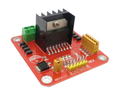
The L298N High-Current Motor Driver Module is a robust and reliable dual-channel H-Bridge driver, designed to act as a powerful interface between your low-voltage microcontroller and high-power motors. Built around the industry-standard ST L298N integrated circuit, this board allows you to independently control the speed and direction of two DC motors, or drive one bipolar stepper motor with precision.
Ideal for robotics, mechatronics projects, and industrial automation, this module simplifies motor control. By accepting standard TTL logic signals (5V) from controllers like Arduino, Raspberry Pi, STM32, or ESP32, it handles the high current requirements of your motors safely. The module includes built-in protection diodes and an optional 5V regulator, making it a complete and user-friendly solution for driving loads up to 35V and 2A.
Key Features
-
Dual H-Bridge Design: Based on the ST L298N chip, featuring two independent H-bridges. Perfect for controlling two DC motors simultaneously (differential drive for robots) or one bipolar stepper motor.
-
High Voltage & Current Handling: Operates with motor supply voltages from 5V to 35V and delivers a continuous 2A current per channel, with peaks up to 3A. Suitable for a wide range of 5V, 12V, and 24V motors.
-
PWM Speed Control: Dedicated Enable pins (ENA & ENB) allow for precise speed regulation via Pulse Width Modulation (PWM) from your microcontroller, enabling smooth acceleration and deceleration curves.
-
Onboard 5V Regulator: Features a built-in 78M05 voltage regulator. When the jumper is active, it can provide 5V power for the logic side directly from the motor supply (provided the supply is between 7V and 35V).
-
Integrated Protection: Includes flyback (snubber) diodes for each output, protecting the IC from voltage spikes generated by motor inductance during operation.
-
Clear Status LEDs: Onboard LEDs indicate power presence and motor direction activity, making troubleshooting and operation monitoring simple.
-
Easy-Terminal Connections: Heavy-duty screw terminals provide secure, reliable connections for power supplies and motor wires, ensuring stability even in high-vibration environments.
-
Standard Logic Interface: Control inputs are TTL-compatible (5V), allowing for direct connection to most microcontrollers without additional level shifting.
Technical Specifications
Pinout & Interface Guide
Understanding the pinout is essential for successful integration.
Power Section
-
VCC (+12V/GND): Main screw terminal for motor power. Connect your battery or external power supply (5V-35V) here.
-
GND: Common ground. Must be connected to the ground of your microcontroller.
-
+5V: Dual-function pin controlled by the 5V-EN jumper.
-
Jumper ON (7V < VCC < 35V): Acts as a 5V OUTPUT. Powers the logic circuit. Can also power a low-current microcontroller.
-
Jumper OFF (VCC < 7V or to use external logic): Acts as a 5V INPUT. You must supply a regulated 5V to this pin.
Motor Outputs
-
OUT1, OUT2: Connection points for first DC motor (Motor A) or one coil of a stepper motor.
-
OUT3, OUT4: Connection points for second DC motor (Motor B) or the second coil of a stepper motor.
Control Pins
-
IN1, IN2: Logic inputs for controlling the direction of Motor A.
-
IN3, IN4: Logic inputs for controlling the direction of Motor B.
-
ENA: Enable A. Connect to a PWM-capable pin on your microcontroller to control the speed of Motor A. (Jumper ON = Full speed).
-
ENB: Enable B. Same function as ENA, for Motor B.
Usage Guide
Typical Wiring Diagram (Arduino + 12V Motors)
Control Logic Table (DC Motor)
(Same logic applies to Motor B using ENB, IN3, IN4)
Q: What motors can I use with this driver?
This module is designed for brushed DC motors and bipolar stepper motors. It is not suitable for brushless DC motors (BLDC) or servo motors.
Q: Can I use this with a 3.3V microcontroller (e.g., ESP32, Raspberry Pi Pico)?
Yes, but we recommend using a logic level shifter to boost the 3.3V signals to 5V for maximum reliability. While the L298N’s logic high threshold is technically 2.3V, using 3.3V signals can sometimes lead to erratic behavior under load or noise.
Q: Is this driver suitable for industrial applications?
Yes, for light industrial tasks or prototyping. However, for continuous high-load industrial use, consider that the L298N is a linear driver and can generate significant heat. Proper heat sinking and derating (reducing current at high temperatures) may be required.
Q: My motors run slowly or won't start. What's wrong?
This is typically a power issue. Check:
-
Power Supply: Ensure your battery/power supply can deliver enough current for both motors starting simultaneously.
-
Grounding: Confirm the L298N GND is connected to the microcontroller GND.
-
Voltage Drop: The L298N has an internal voltage drop of ~2V. If your motor is rated for 6V, you may need to supply 8-9V to the VCC terminal to achieve rated speed.
Q: My microcontroller resets when the motors turn on.
This is caused by voltage sag from high inrush current. Add a large electrolytic capacitor (470µF to 1000µF, 50V) across the VCC and GND terminals of the L298N to stabilize the voltage.
Q: The module gets very hot. Is this normal?
It will get warm during normal operation. If it is extremely hot to the touch, you are likely drawing too much current. Check for mechanical binding in your robot, reduce the load, or add active cooling (a small fan).
Q: The LEDs light up, but the motors don't move.
This usually points to the Enable pins.
Q: My motors only spin in one direction.
Verify your code is correctly changing the states of the IN pins. For reverse, you must have the opposite logic (e.g., IN1=LOW, IN2=HIGH) compared to forward (IN1=HIGH, IN2=LOW).
Q: What happens if I use a motor supply over 12V with the 5V jumper ON?
You will damage the onboard 5V regulator. If your motor supply is above 12V, you MUST remove the 5V-EN jumper and supply a separate, regulated 5V to the +5V pin.