Product Overview
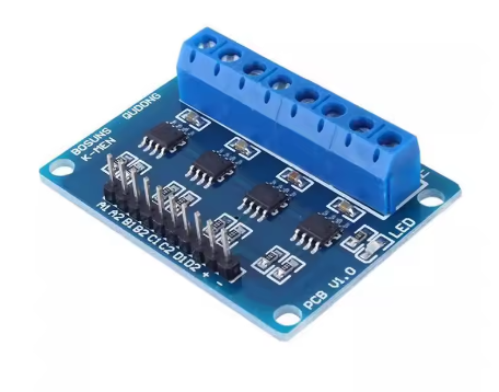
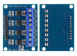
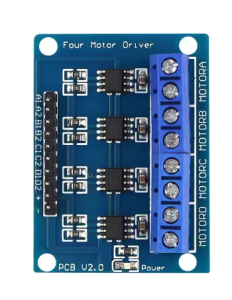
The L9110S 4-Channel DC Motor Drive Board is a compact and powerful motor driver module designed to control up to four DC motors simultaneously . Built around multiple L9110S H-bridge driver chips, this board provides an efficient solution for robotics projects, smart car platforms, and automation systems requiring multiple motors.
Each channel on this board can independently control a DC motor’s speed and direction, making it ideal for complex motion control applications such as Mecanum wheel robots, omnidirectional platforms, or multi-axis automation systems . The board operates on a wide voltage range of 2.5V to 12V, supporting both 3.7V lithium batteries and 5V/12V power supplies .
With a clean interface design, this module simplifies the wiring complexity of multi-motor projects. All control pins are arranged systematically, allowing direct connection to microcontrollers like Arduino, ESP32, or STM32. The board also provides screw terminals for secure motor wire connections, ensuring reliable operation even in vibration-prone environments .
Key Features
-
4 Independent Motor Channels: Controls up to four DC motors simultaneously, perfect for Mecanum wheel robots and complex automation systems
-
Wide Operating Voltage: Supports 2.5V to 12V DC input, compatible with 3.7V Li-ion, 5V USB, and 12V power supplies
-
800mA Continuous Output Current: Each channel delivers up to 800mA continuous current (1.5A peak), suitable for small to medium DC motors
-
Independent Speed and Direction Control: Each motor channel supports PWM speed control and forward/reverse direction switching
-
Low Standby Current: Minimal power consumption when motors are idle, ideal for battery-powered applications
-
Built-in Flyback Diodes: Integrated protection diodes suppress voltage spikes from motor inductance, safeguarding your control circuit
-
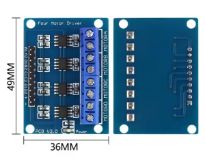
Compact Design: Small footprint allows easy integration into space-constrained robot chassis and enclosures
-
Easy Wiring via Screw Terminals: Individual terminal blocks for each motor provides secure, tool-friendly connections
Technical Specifications
Pinout & Interface Guide
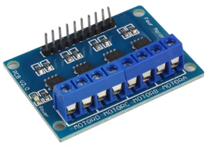
The board features a systematic 8-pin control interface and four motor terminal blocks:
Control Pins (Connect to Microcontroller)
Motor Output Terminals (Screw Terminal Blocks)
Control Truth Table (Per Channel)
Usage Guide
Wiring Instructions
IMPORTANT: Always disconnect the input power source before wiring or modifying connections.
Step 1: Connect Motor Power
Step 2: Connect Motors
-
Connect the two wires of Motor A to the Motor A screw terminals (polarity determines initial rotation direction).
-
Connect Motors B, C, and D similarly to their respective terminals .
Step 3: Connect Control Signals
-
Connect the 8 control pins (A1/A2, B1/B2, C1/C2, D1/D2) to digital pins on your microcontroller (Arduino, ESP32, etc.) .
Step 4: Common Ground
Power Supply Considerations
-
Power Source Selection: For 4 motors running simultaneously, ensure your power supply can deliver sufficient total current (up to 3.2A continuous with all motors at full load).
-
Voltage Matching: Choose a voltage within 2.5V-12V that matches your motors’ specifications.
-
Decoupling Capacitors: Adding a 100µF-470µF electrolytic capacitor across VCC and GND can stabilize voltage during sudden current spikes .
Complete Arduino Example Code (4 Motors)
const int motorA_IA = 3;
const int motorA_IB = 4;
const int motorB_IA = 5;
const int motorB_IB = 6;
const int motorC_IA = 7;
const int motorC_IB = 8;
const int motorD_IA = 9;
const int motorD_IB = 10;
void setup() {
pinMode(motorA_IA, OUTPUT);
pinMode(motorA_IB, OUTPUT);
pinMode(motorB_IA, OUTPUT);
pinMode(motorB_IB, OUTPUT);
pinMode(motorC_IA, OUTPUT);
pinMode(motorC_IB, OUTPUT);
pinMode(motorD_IA, OUTPUT);
pinMode(motorD_IB, OUTPUT);
}
void setMotor(int IA, int IB, int speed, bool forward) {
if (forward) {
analogWrite(IA, speed);
digitalWrite(IB, LOW);
} else {
digitalWrite(IA, LOW);
analogWrite(IB, speed);
}
}
void stopMotor(int IA, int IB) {
digitalWrite(IA, LOW);
digitalWrite(IB, LOW);
}
void loop() {
setMotor(motorA_IA, motorA_IB, 178, true);
setMotor(motorB_IA, motorB_IB, 178, true);
setMotor(motorC_IA, motorC_IB, 178, true);
setMotor(motorD_IA, motorD_IB, 178, true);
delay(3000);
stopMotor(motorA_IA, motorA_IB);
stopMotor(motorB_IA, motorB_IB);
stopMotor(motorC_IA, motorC_IB);
stopMotor(motorD_IA, motorD_IB);
delay(2000);
setMotor(motorA_IA, motorA_IB, 127, false);
setMotor(motorB_IA, motorB_IB, 127, false);
setMotor(motorC_IA, motorC_IB, 127, false);
setMotor(motorD_IA, motorD_IB, 127, false);
delay(3000);
digitalWrite(motorA_IA, HIGH);
digitalWrite(motorA_IB, HIGH);
digitalWrite(motorB_IA, HIGH);
digitalWrite(motorB_IB, HIGH);
digitalWrite(motorC_IA, HIGH);
digitalWrite(motorC_IB, HIGH);
digitalWrite(motorD_IA, HIGH);
digitalWrite(motorD_IB, HIGH);
delay(2000);
}
Q: How many motors can this board control?
This board can independently control up to 4 DC motors. Each channel has its own H-bridge circuit and control pins .
Q: Can I control stepper motors with this board?
Yes. You can drive two 4-wire bipolar stepper motors (using two channels per stepper motor) or a single stepper motor if you only need one .
Q: What voltage should I use for my motors?
The board accepts 2.5V to 12V DC. Choose a voltage that matches your motor’s rated voltage. Common options include 3.7V (Li-ion), 5V (USB), 6V, 7.4V (2S Li-ion), or 12V .
Q: How much current can each motor channel provide?
Each channel provides 800mA continuous current and can handle 1.5A peak current for short durations . For motors requiring higher current, consider using an external power relay or a higher-rated driver.
Q: Is this board compatible with 3.3V microcontrollers like ESP32?
Yes. The control logic is compatible with both 3.3V and 5V logic levels, making it suitable for Arduino, ESP32, STM32, and Raspberry Pi Pico .
Q: What power supply should I use for 4 motors?
The total current requirement depends on your motors. For example, with 4 motors each drawing 500mA, you need a power supply capable of delivering at least 2A. Add a 20-30% safety margin. A 3A or higher supply is recommended .
Q: Why do my motors run slowly or stop under load?
This typically indicates insufficient power. Check that:
-
Your power supply can deliver enough current for all motors combined
-
The voltage measured at the VCC terminal doesn’t drop significantly under load
-
Battery voltage matches motor specifications
Q: Does the module get hot during operation?
Some warmth is normal. At 800mA per channel, the L9110S IC will generate heat. If it becomes too hot to touch, ensure adequate airflow and verify that current draw does not exceed the 800mA continuous rating .
Q: Can I use a higher voltage than 12V?
No. Exceeding 12V can permanently damage the L9110S chips. The absolute maximum rating is 12V .
Q: The module has power but motors don't move. What should I check?
Follow this checklist:
-
Ensure GND of driver board is connected to GND of microcontroller
-
Verify VCC voltage at the driver board terminals (2.5V-12V)
-
Check that control pin connections are correct (IA to microcontroller output)
-
Confirm your code is sending the correct signals (HIGH/LOW/PWM)
Q: Why do my motors run in the wrong direction?
This is easily fixed. You can either:
Q: Can I use this board without a microcontroller?
Yes. You can test motors by manually connecting IA to VCC (forward) or GND (stop), and IB similarly for reverse. For practical projects, a microcontroller is recommended for speed control and automation.
Q: What is the difference between L9110 and L9110S?
The L9110 and L9110S are functionally identical. The “S” typically indicates the surface-mount package version (SOIC-8). Both offer the same 800mA/1.5A current specifications .
Q: What can I build with this 4-channel L9110S board?
Popular applications include:
-
Mecanum wheel robots (requires 4 independent motors for omnidirectional movement)
-
4WD smart cars and off-road vehicles
-
Conveyor belt systems with multiple drive points
-
Automated window blinds or curtain openers
-
Multi-pump irrigation controllers for automated plant watering
-
Camera gimbals and pan-tilt mechanisms
-
Educational robotics for teaching motor control principles
Q: Is this board suitable for robot competitions?
Yes. The 4 independent channels make it ideal for Mecanum wheel robots and 4WD platforms in robotics competitions. Ensure your motors stay within the 800mA continuous rating per channel