LCR-T4 Graphical Transistor Tester with Capacitance/ESR/Silicon Controlled Rectifier (SCR) Measurement

SKU: FA1061-2
Microcontroller

ATmega328P

Display

128×64 Graphical LCD with Backlight

Power Supply

9V Battery (6F22) or 8.4V Li-ion Battery Pack

Resistance Range

0.1Ω to 50MΩ

Capacitance Range

25pF to 100,000μF (100mF)

Inductance Range

0.01mH to 20H

Operating Current

~25mA

Shutdown Current

20nA (supports long-term battery storage)

Product Description
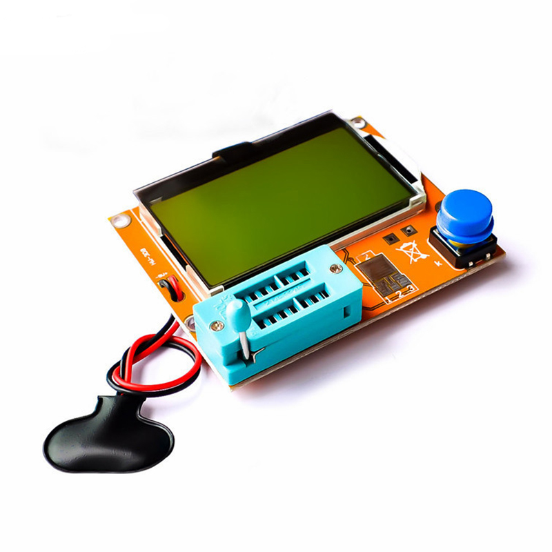
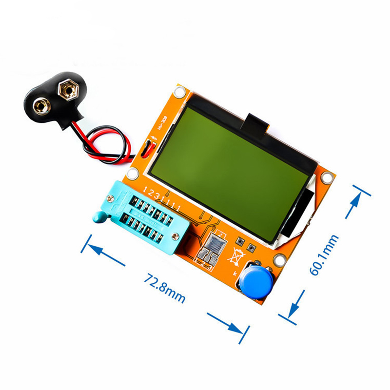
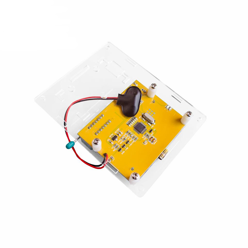
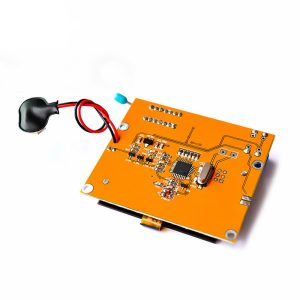
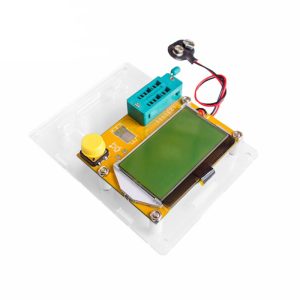
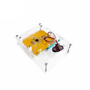
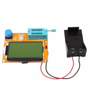
The LCR-T4 is an intelligent semiconductor analyzer designed to simplify component identification and troubleshooting. Featuring a high-resolution 128×64 yellow-green backlit LCD, it provides intuitive graphical representations of pinouts and measurement data. This “electronic microscope” for circuits can detect hidden faults in aged capacitors by measuring Equivalent Series Resistance (ESR) and is highly effective for pairing transistors or identifying unknown Surface Mount Devices (SMD). Its ultra-low power consumption and automatic shutdown make it ideal for portable field use or long-term bench work.
Key Features
  • Universal Compatibility: Automatically detects NPN/PNP transistors, N-channel/P-channel MOSFETs, JFETs, diodes (including dual diodes), and Silicon Controlled Rectifiers (SCRs/Thyristors).
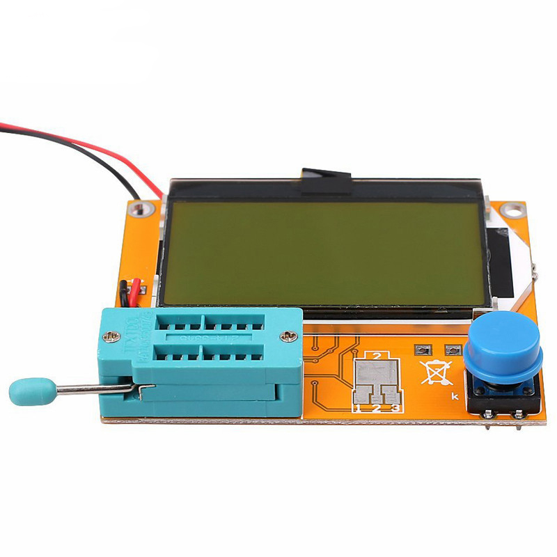
  • Intelligent Pinout Identification: Automatically identifies and displays component pin arrangements (e.g., Base, Collector, Emitter) on the screen, removing the need for manual datasheets.
  • Precision Measurement: Measures current amplification factors (hFE) and base-emitter threshold voltages for bipolar transistors.
  • Enhanced Capacitor Analysis: For capacitors over 2μF, the device simultaneously measures ESR with a resolution of 0.01Ω.
  • One-Button Operation: Fully automated testing cycle completes in approximately 2 seconds (larger capacitors may take up to 1 minute).
Usage Instructions
  1. Preparation: Insert a 9V battery. Critical: Always discharge capacitors before testing to avoid damaging the tester’s internal circuitry.
  2. Testing: Place the component leads into the ZIF socket (using ports 1, 2, or 3) and lock the lever. Press the start button.
  3. Reading: The device will power on, detect the component type, and display the values and pinout. It will automatically shut down after a period of inactivity.
  4. Calibration: To calibrate (Self-Test), short all three test ports (1, 2, and 3) with a wire and press the button. Follow the on-screen prompts to “isolate probes” and eventually insert a non-polar capacitor (>100nF) when requested.
Q: Can I use this for business/professional repairs?

Yes. It is an excellent tool for rapid triage and “normality” checks in repair shops. However, for high-precision laboratory standards or extremely high-voltage testing, it is often used as a supplementary tool alongside professional oscilloscopes.

Q: Why does the screen say "isolate probes" during calibration?

This is part of the self-test sequence. Once you see this message, remove the shorting wires from the test ports so the device can measure its own internal resistance and zero out the readings.

Q: Can it test components while they are still soldered to a circuit board?

No. For accurate results and to protect the device, components should be desoldered and tested individually. Testing in-circuit can lead to false readings due to parallel paths in the circuit.

Q: What should I do if the screen contrast is too low?

Some models allow contrast adjustment through the internal menu (long-press the button to enter the menu) or by adjusting a small potentiometer on the back of the PCB, depending on the specific assembly version.