Product Overview
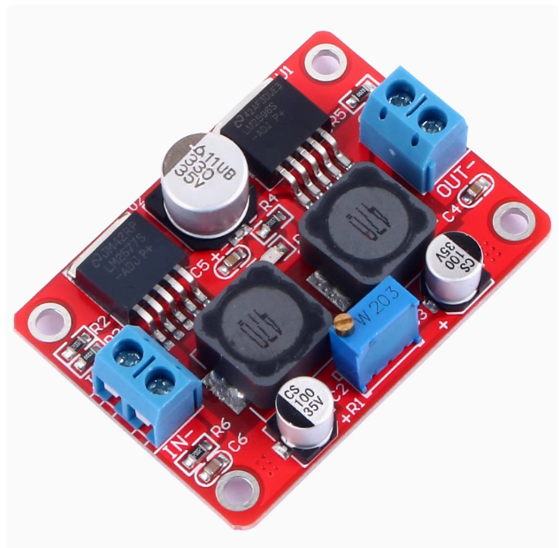
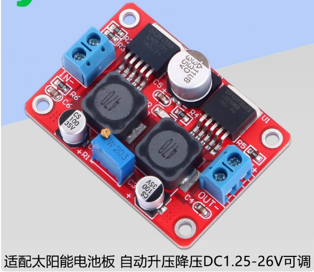
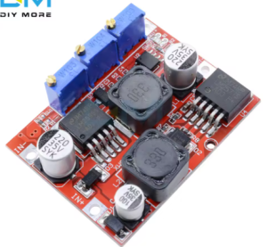
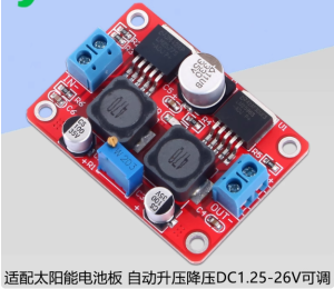
The LM2577S + LM2596S Auto Step-Up/Down Voltage Regulator Module is a versatile buck-boost converter that combines two industry-standard switching regulators into one compact board. This module can automatically step up (boost) or step down (buck) an input voltage to a stable, user-defined output level, making it ideal for applications where the power source voltage fluctuates—such as solar panels, wind generators, or automotive systems .
Unlike standard voltage regulators that only step down (buck) or step up (boost), this module does both. If your input voltage is 24V and you need 12V, it bucks down; if your input is 5V and you need 12V, it boosts up. This automatic functionality ensures your output remains stable even as the input varies .
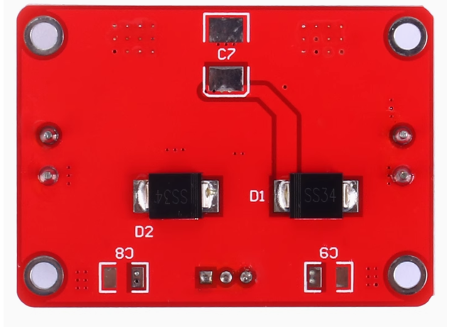
The module is built around the LM2596S (buck converter) and LM2577S (boost converter) ICs from Texas Instruments. It features Constant Current/Constant Voltage (CC/CV) control with dedicated indicator LEDs, making it particularly well-suited for battery charging applications—including lithium, lead-acid, nickel-cadmium, and nickel-metal hydride batteries . The onboard trimpots allow independent adjustment of output voltage (CV), constant current limit (CC), and the transition current at which the charging LED indicates completion .
With an input range of 4V to 35V and an adjustable output range of 1.25V to 25V (or up to 26V on some variants), this module is a practical choice for DIY power supplies, solar charge controllers, LED drivers, and battery charging systems .
Key Features
-
Automatic Buck-Boost Operation: Automatically steps up (boosts) or steps down (bucks) input voltage (4-35V) to maintain a stable output between 1.25-25V, regardless of input fluctuations .
-
CC/CV (Constant Current/Constant Voltage) Control: Enables precise battery charging with adjustable constant current (0-2A) and constant voltage, protecting batteries from overcharging .
-
Dual-Chip Design: Combines LM2596S (step-down) and LM2577S (step-up) regulators for reliable performance in both operating modes .
-
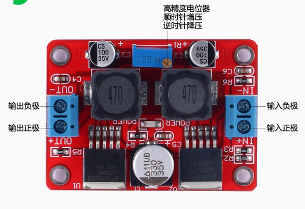
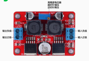
Three Adjustable Potentiometers: Independent trimpots for output voltage (CV), constant current limit (CC), and revolving light current (transition point from CC to CV mode) .
-
Dual-Color Charging Status Indicators: Red LED indicates charging in progress/constant current mode; Blue LED indicates charging complete (constant voltage mode) .
-
15W Output Power: Capable of delivering up to 15W under natural cooling; add a heatsink for operation beyond 15W .
-
3A Maximum Output Current: Supports up to 3A output current (derate based on input-output voltage differential) .
-
Wide Operating Temperature: Industrial grade rated from -40°C to +85°C; above 40°C ambient, reduce power or add a heatsink .
-
Output Short Circuit Protection: Constant current protection activates during output short circuits .
Technical Specifications
Pinout & Interface Guide
Connection Terminals
User Controls (Potentiometers)
Status Indicators
Usage Guide
Wiring Instructions
IMPORTANT: Always disconnect the input power source before wiring. Do not reverse polarity—this module does not have built-in reverse polarity protection .
CRITICAL WARNING: Do not connect the GND of the OUTPUT to the GND of the INPUT. These must remain isolated for proper operation .
Basic Connection
-
Connect Input: Connect your DC power source (solar panel, battery, power supply) to IN+ and IN- .
-
Connect Output: Connect your load (battery, LED, device) to OUT+ and OUT- .
-
Adjust Settings: Follow the calibration procedure below before connecting sensitive loads.
Calibration Procedure
For Battery Charging Applications
-
Determine Battery Parameters: Identify your battery’s float voltage (e.g., 12.6V for 3S Li-ion, 13.8V for 12V lead-acid) and desired charge current (e.g., 1A).
-
Set Initial Output: Turn the CV potentiometer counter-clockwise to lower output voltage to approximately 3V .
-
Set Charge Current: Short the output terminals with a multimeter in 10A current mode. Adjust the CC potentiometer clockwise until the meter reads your desired charge current .
-
Set Float Voltage: Remove the short, connect a multimeter to output terminals. Adjust the CV potentiometer clockwise until the voltage reaches your battery’s float voltage .
-
Verify Charging: Connect your battery and monitor. Red LED indicates charging; Blue LED indicates fully charged .
For LED Constant Current Driver Applications
-
Determine LED Requirements: Identify LED operating current and maximum forward voltage.
-
Set LED Current: Short the output terminals with a multimeter in 10A current mode. Adjust the CC potentiometer clockwise until current reaches desired LED operating current .
-
Set Maximum Voltage: Remove the short, connect a multimeter. Adjust the CV potentiometer clockwise until voltage reaches LED’s maximum forward voltage .
-
Connect LED: Connect your LED array and verify operation.
Potentiometer Adjustment Direction
Solar Panel Usage Notes
When using solar panels as the power source, ensure:
-
Input power is sufficient for your output requirements; the module cannot create power, only convert it.
-
Solar panel voltage stays within the 4-35V input range.
-
The module is ideal for applications with fluctuating input voltage, such as solar or wind systems .
Important Considerations
-
Heat Management: For continuous operation above 15W, install a heatsink on the main switching IC .
-
Reverse Polarity: This module has no reverse polarity protection; double-check your wiring before applying power .
-
Output Ground Isolation: The output GND must not be connected to input GND .
-
Minimum Load: Some configurations may require a minimum load for stable regulation.
-
Efficiency: Efficiency is typically around 80%; higher output voltages yield higher efficiency
Q: What is the difference between buck and boost conversion?
Buck conversion (step-down) reduces a higher input voltage to a lower output voltage (e.g., 24V to 12V). Boost conversion (step-up) increases a lower input voltage to a higher output voltage (e.g., 5V to 12V). This module automatically handles both functions
Q: What is the advantage of this module over separate buck or boost converters?
This module provides both functions in one board, automatically adjusting to maintain a stable output regardless of input fluctuations. This is essential for solar/wind applications where input voltage varies significantly
Q: What is the maximum output current?
The module is rated for 3A maximum output current. However, output power is limited to 15W under natural cooling, so maximum current depends on output voltage (15W / output voltage = maximum current)
Q: Can I use this module with a 24V solar panel?
Yes. The module accepts 4-35V input, making it compatible with 12V, 24V, and even 36V solar panels
Q: What is the purpose of the third potentiometer (revolving light current)?
This pot adjusts the transition point at which the charging LED switches from red (charging) to blue (full). It is typically set to 10% of the constant current value but can be adjusted from 1% to 100%
Q: The module gets hot. Is this normal?
Some heat is normal under load. The module is rated for 15W natural cooling. If operating above 15W or if the module is too hot to touch, add a heatsink to the main switching IC
Q: What is the efficiency of this converter?
Conversion efficiency is up to 80%. Higher output voltages generally yield higher efficiency
Q: Why is my output voltage not changing when I turn the potentiometer?
The potentiometer may require multiple rotations. Try turning it counter-clockwise 20 or more full rotations, then adjust clockwise while monitoring with a multimeter
Q: Why does the output voltage equal the input voltage and won't adjust?
This usually indicates the module is not regulating properly. Check that your input voltage is within the 4-35V range and that you have not shorted the output. Try turning the CV potentiometer counter-clockwise many turns, then adjust clockwise
Q: The module has power but no output. What's wrong?
Follow this checklist:
-
Check that input voltage is between 4-35V .
-
Verify polarity (IN+ to positive, IN- to negative)—the module has no reverse protection .
-
Check that output is not shorted.
-
Adjust CV potentiometer clockwise (may require multiple turns).
-
If charging a fully charged battery, the blue LED will be on but output current will be minimal.
Q: What do the indicator LEDs mean?
– Red CC LED ON: Module is in constant current mode .
Q: Can I connect the input and output grounds together?
No. Do not connect the GND of the OUTPUT to the GND of the INPUT. These must remain isolated for proper operation
Q: Can I run two modules in parallel for more current?
Not recommended. Running switching regulators in parallel without current-sharing circuitry can cause one module to supply most of the load, leading to overheating and failure. For higher current, use a single higher-rated converter
Q: What can I build with this module?
Popular applications include:
-
Solar battery chargers for 12V/24V lead-acid or lithium batteries .
-
Wind turbine voltage regulators for battery charging systems .
-
High-power LED drivers with constant current control .
-
DIY variable bench power supplies (1.25-25V, 0-2A adjustable) .
-
Car power voltage stabilizers for fluctuating vehicle electrical systems.
Q: Is this module suitable for charging lithium batteries?
Yes. The CC/CV charging profile is ideal for lithium batteries. Set the float voltage to 4.2V per cell (e.g., 12.6V for 3S Li-ion) and current to the recommended charge rate
Q: Can I use this module as a general-purpose power supply?
Yes. With adjustable output from 1.25V to 25V and constant current limiting, it serves as an excellent variable bench power supply for testing and powering electronics projects
Q: Can I charge a 12V lead-acid battery with this module?
Yes. Set the output voltage to 13.8V (float charge) or 14.4V (bulk charge) and set the current limit to the battery’s recommended charge rate (typically 10-20% of Ah rating)