Description
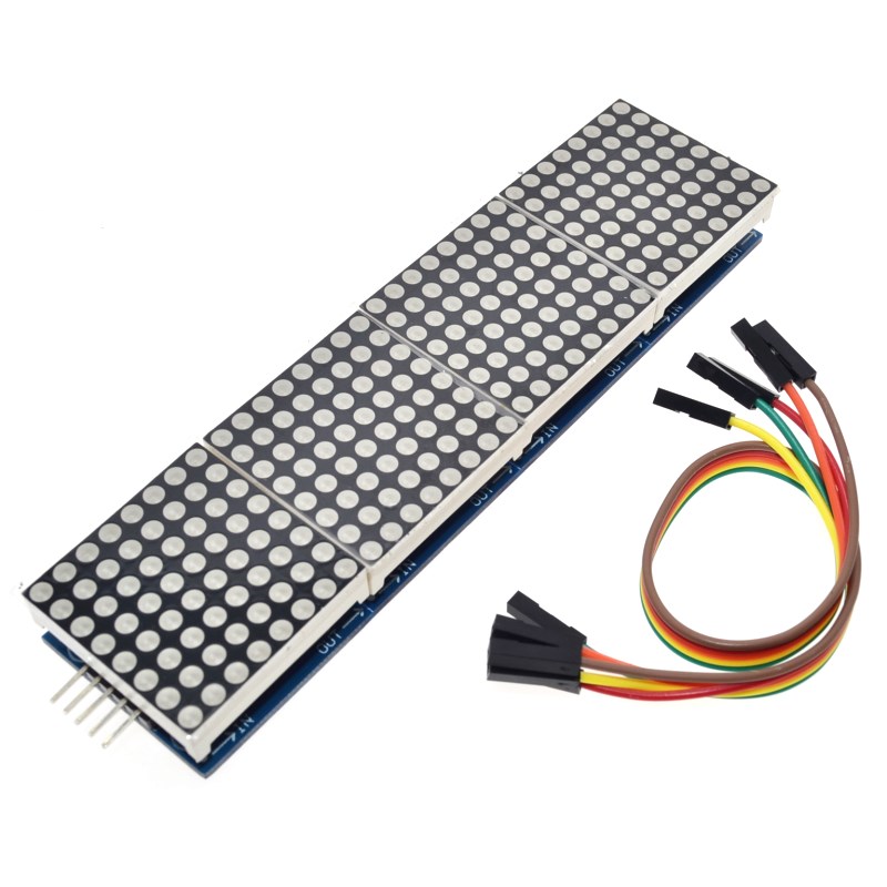
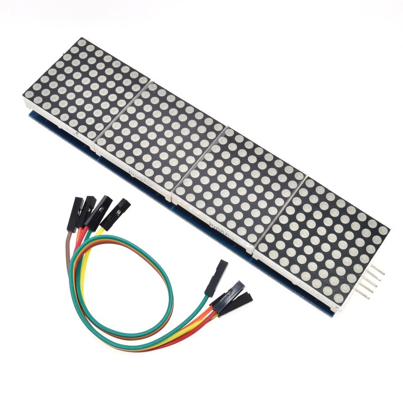
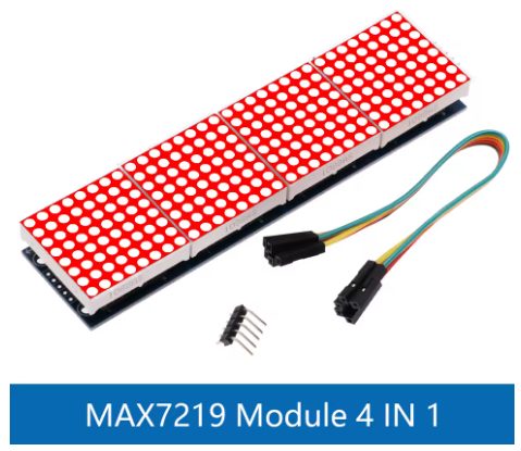
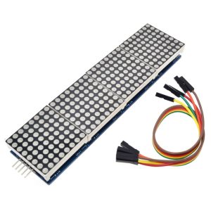
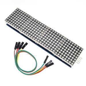
The MAX7219 4-in-1 Dot Matrix Display Module is a powerful and versatile LED display solution designed for microcontroller-based projects, electronic signage, and visual information systems. This module integrates four individual 8×8 red LED dot matrix panels into a single compact unit, creating a combined display area of 8 LEDs wide by 32 LEDs long (8×32 resolution) . Each of the 256 red LEDs can be individually controlled, enabling the display of scrolling text, static messages, custom graphics, animations, and even simple video game graphics.
At the heart of this module is the MAX7219 integrated circuit driver, a specialized serial input/output common-cathode display driver that significantly simplifies the process of controlling LED matrices . The MAX7219 handles all the complex multiplexing and refresh timing internally, eliminating the need for constant microcontroller intervention and ensuring flicker-free display performance . The driver includes an 8×8 static RAM for storing display data, a BCD decoder, a multiplex scan circuit, and segment drivers—all integrated into a single chip .
The module communicates via a simple 5-wire SPI interface (VCC, GND, DIN, CS, CLK), requiring only three I/O pins from your microcontroller to control all 256 LEDs . This efficient communication protocol allows the module to be easily integrated with popular development platforms including Arduino, Raspberry Pi, ESP8266, ESP32, STM32, and other SPI-compatible microcontrollers. The module also features input and output headers on opposite sides, allowing multiple units to be cascaded in a daisy-chain configuration to create larger displays .
Key design benefits include:
-
Flicker-free operation – The MAX7219 automatically refreshes the display at high frequency
-
Software-controlled brightness – 16 discrete brightness levels from 0 to 15
-
Low microcontroller overhead – SPI communication minimizes CPU usage
-
Cascading capability – Connect multiple modules to build larger displays
-
Low power consumption – Typical operating current of 30-80mA at 5V
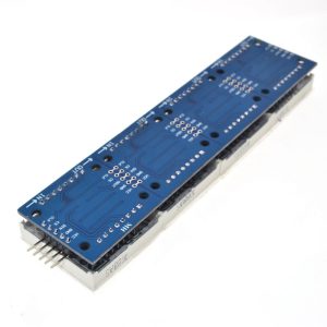
The module is constructed on a durable PCB with four 3mm mounting holes at each corner, making it easy to secure to enclosures, panels, or custom mounting brackets . The red LEDs provide excellent visibility even in ambient light conditions, making this module suitable for both indoor and covered outdoor applications.
Whether you need to build a scrolling message board for retail signage, a real-time data display for IoT projects, a scoreboard for sports events, a status indicator for industrial equipment, or simply want to add dynamic visual output to your next electronics project, the MAX7219 4-in-1 Dot Matrix Display Module delivers reliable, bright, and easy-to-control LED display capability at an affordable price.
Key Features
-
4-in-1 Integrated Design – Four 8×8 dot matrix modules pre-assembled into a single 8×32 pixel display panel (256 total LEDs)
-
MAX7219 Driver Chip – Handles all multiplexing and refresh timing automatically for flicker-free display
-
Simple SPI Interface – Only 3 I/O pins required to control all 256 LEDs (DIN, CS, CLK)
-
Software Brightness Control – 16 adjustable brightness levels via register setting (0x0 to 0xF)
-
Cascadable Design – Input and output headers allow multiple modules to be daisy-chained for larger displays
-
5V Operating Voltage – Compatible with 5V microcontrollers; 3.3V logic devices require level shifting
-
Red LED Color – High-visibility red LEDs with excellent brightness and viewing angle
-
Compact Dimensions – 128 x 32 x 12mm (L x W x H) with 3mm mounting holes at each corner
-
Individual LED Control – Each of the 256 LEDs can be addressed independently
-
Library Support – Extensive community libraries available (MD_Parola, LedControl, MD_MAX72XX)
Technical Parameters
Usage Guide
Hardware Overview
The module consists of four individual 8×8 LED matrix panels arranged in a line, each driven by its own MAX7219 chip. The modules are pre-wired in a cascade configuration, with data flowing from one module to the next .
Component Identification:
-
LED Panels: Four 8×8 red LED matrices (8 columns × 32 rows total)
-
MAX7219 ICs: Four driver chips (one per matrix, located on the back of the PCB)
-
Input Header (5 pins) : Connects to your microcontroller
-
Output Header (5 pins) : For cascading to additional modules
Pinout Description
The module uses a standard 5-pin header (2.54mm pitch) for connections:
Wiring Instructions
Step 1 – Connect to Microcontroller
Arduino Uno/Nano Connection:
ESP8266/ESP32 Connection:
Raspberry Pi Connection:
⚠️ Important: For Raspberry Pi and other 3.3V logic devices, the MAX7219 requires 5V power, but the logic signals (DIN, CS, CLK) should be level-shifted from 3.3V to 5V for reliable operation . While some users report success without level shifting, voltage level converters are recommended for production installations.
Step 2 – Power Considerations
-
A single 4-in-1 module draws approximately 30-80mA under normal operation
-
Maximum current can reach 320mA when all LEDs are illuminated at full brightness
-
Most microcontroller 5V pins can supply 400-500mA, sufficient for one module
-
For cascaded modules or high-brightness applications, use an external 5V power supply
Cascading Multiple Modules
To create larger displays, connect additional modules in a daisy chain:
-
Connect the output header of the first module to the input header of the second module
-
Match pins: VCC→VCC, GND→GND, DIN→DIN, CS→CS, CLK→CLK
-
Update the MAX_DEVICES parameter in your code to match the total number of modules
Cascading Example:
-
1 module = 8×32 pixels
-
2 modules = 8×64 pixels
-
4 modules = 8×128 pixels
Software Setup
Arduino – LedControl Library
-
Install Library: Open Arduino IDE → Tools → Manage Libraries → Search “LedControl” → Install
-
Basic Initialization Code:
#include "LedControl.h"
LedControl lc = LedControl(11, 13, 10, 4);
void setup() {
for (int module = 0; module < 4; module++) {
lc.shutdown(module, false);
lc.setIntensity(module, 2);
lc.clearDisplay(module);
}
}
void loop() {
lc.setLed(0, 0, 0, true);
delay(500);
lc.setLed(0, 0, 0, false);
delay(500);
}
Arduino – MD_Parola Library (Scrolling Text)
For advanced scrolling text effects, install both MD_Parola and MD_MAX72XX libraries :
#include <MD_Parola.h>
#include <MD_MAX72xx.h>
#include <SPI.h>
#define HARDWARE_TYPE MD_MAX72XX::FC16_HW
#define CS_PIN 10
#define MAX_DEVICES 4
MD_Parola display = MD_Parola(HARDWARE_TYPE, CS_PIN, MAX_DEVICES);
void setup() {
display.begin();
display.setIntensity(8);
display.displayClear();
}
void loop() {
display.displayScroll("Hello World!", PA_CENTER, PA_SCROLL_LEFT, 100);
while (!display.displayAnimate()) { }
delay(1000);
}
Important Note on Hardware Type: If the displayed text appears reversed or upside down, change the HARDWARE_TYPE definition :
-
#define HARDWARE_TYPE MD_MAX72XX::FC16_HW (most common for blue/red PCBs)
-
#define HARDWARE_TYPE MD_MAX72XX::PAROLA_HW
-
#define HARDWARE_TYPE MD_MAX72XX::ICSTATION_HW
Display Patterns and Custom Characters
Each 8×8 module is organized as 8 rows of 8 columns. To create custom patterns:
byte smiley[8] = {
B00111100,
B01000010,
B10100101,
B10000001,
B10100101,
B10011001,
B01000010,
B00111100
};
for (int row = 0; row < 8; row++) {
lc.setRow(0, row, smiley[row]);
}
Installation Tips
-
Mounting: Secure using M3 screws through the four corner mounting holes (3mm diameter)
-
Ventilation: Ensure adequate airflow around the module, especially in cascaded configurations
-
Cable Length: Keep SPI wires as short as possible (under 50cm) to prevent signal degradation
-
Level Shifting: For 3.3V microcontrollers, use a 4-channel bi-directional logic level converter
-
Enclosure: For outdoor installations, protect the module in a weatherproof enclosure
Q: What is the difference between this 4-in-1 module and four separate 8x8 modules?
The 4-in-1 module comes pre-assembled with four 8×8 matrices on a single PCB, saving you assembly time and ensuring proper alignment. The electrical connection is equivalent to four separate modules cascaded together, and the software treats it as four devices
Q: Can I use this module with 3.3V microcontrollers like Raspberry Pi or ESP32?
The MAX7219 requires 5V power for reliable operation. For 3.3V logic devices:
-
Power: Connect VCC to 5V (from external supply or 5V pin)
-
Signals: Use a logic level converter for DIN, CS, and CLK pins
-
While some users report success without level shifting, it is not recommended for production use
Q: What library should I use for Arduino?
Two popular libraries are:
-
LedControl: Simple, good for basic patterns and custom animations
-
MD_Parola (with MD_MAX72XX): Advanced scrolling text effects, multiple fonts, and alignment options
Q: Why is my text displayed backwards or upside down?
This is a common issue caused by incorrect hardware type definition. Try changing the HARDWARE_TYPE in your code :
#define HARDWARE_TYPE MD_MAX72XX::FC16_HW
#define HARDWARE_TYPE MD_MAX72XX::PAROLA_HW
#define HARDWARE_TYPE MD_MAX72XX::ICSTATION_HW
#define HARDWARE_TYPE MD_MAX72XX::GENERIC_HW
Q: Can I cascade multiple 4-in-1 modules together?
Yes. Connect the output header of one module to the input header of the next. Update the MAX_DEVICES parameter in your code to the total number of 8×8 modules (e.g., two 4-in-1 modules = 8 devices) .
Q: How do I control the brightness?
Brightness can be adjusted in software using:
-
LedControl: lc.setIntensity(module, value) where value = 0 (min) to 15 (max)
-
MD_Parola: display.setIntensity(value)
The MAX7219 supports 16 discrete brightness levels
Q: What is the maximum current draw?
-
Normal operation: 30-80mA
-
All LEDs at maximum brightness: up to 320mA
-
For cascaded modules, total current adds: 4 modules (16×16) could draw over 1A at full brightness
Q: Can I use this module for both home and business applications?
Home users: DIY message boards, IoT status displays, clock projects, Christmas decorations, home automation status indicators, retro game displays.
Business users: Retail signage (scrolling promotions), industrial equipment status displays, public transportation information boards, scoreboards, queue management displays, laboratory equipment readouts, manufacturing line status indicators.
Q: Does the module remember the display content after power loss?
No. The MAX7219 has volatile memory. When power is lost, the display content is cleared. Your microcontroller must re-send display data during startup.
Q: What is the viewing angle of the red LEDs?
The 3mm LEDs typically have a wide viewing angle of approximately 120-160 degrees, making the display readable from various positions