Description
Product Overview
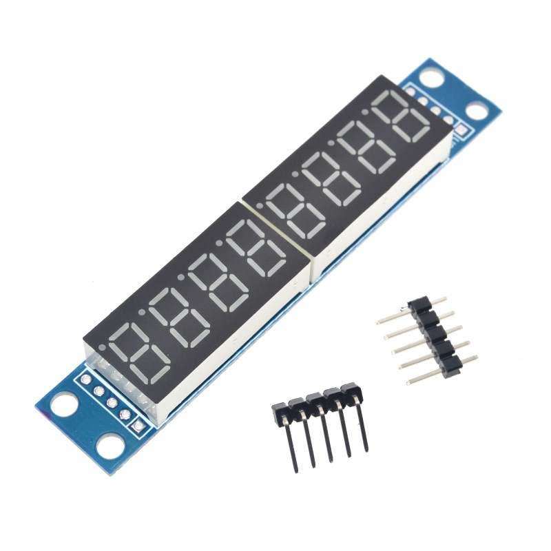
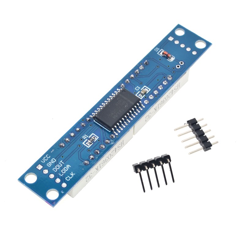
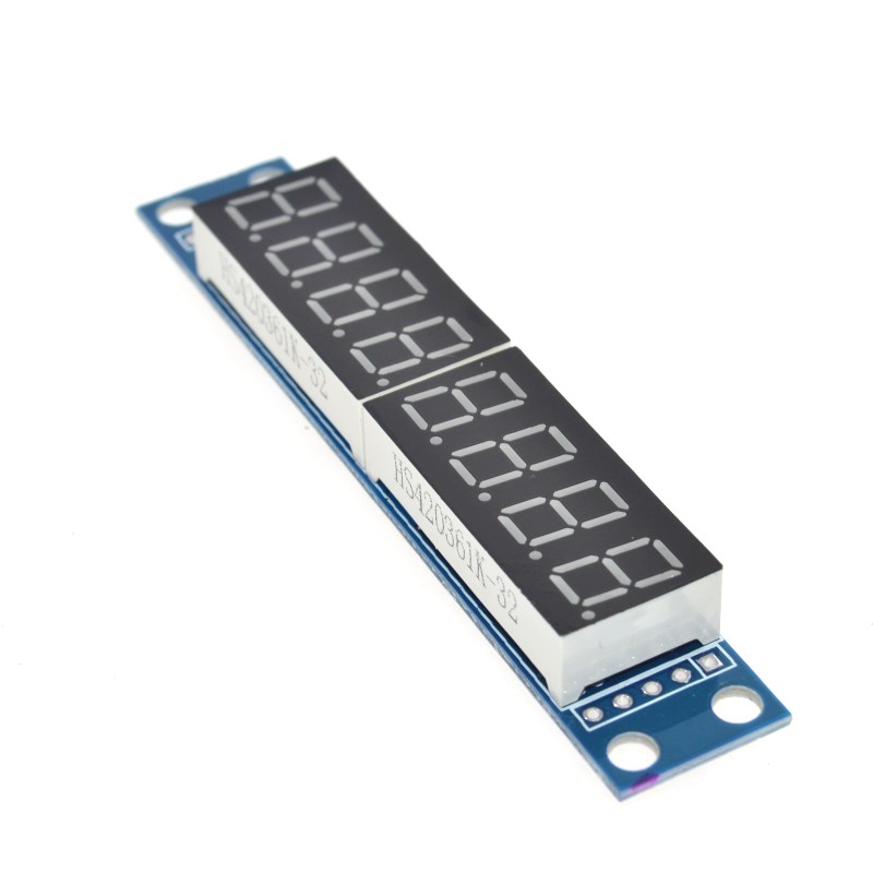
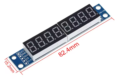
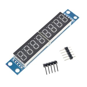
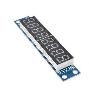
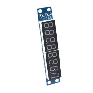
The MAX7219 8-Bit Digital Tube Display Module is a complete, ready-to-use solution for driving eight 7-segment LED displays. Based on the industry-standard MAX7219 driver IC from Maxim Integrated (now Analog Devices), this module allows you to control up to 8 digits using only 3 I/O pins from your microcontroller – a dramatic reduction from the 16+ pins typically required for direct drive .
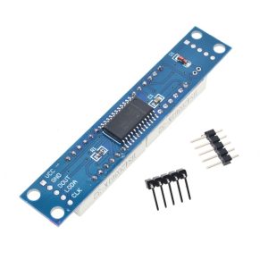
The MAX7219 is a compact, serial input/output common-cathode display driver that interfaces microprocessors to 7-segment numeric LED displays of up to 8 digits, bar-graph displays, or 64 individual LEDs . On-chip features include a BCD code-B decoder, multiplex scan circuitry, segment and digit drivers, and an 8×8 static RAM that stores each digit . Only one external resistor is required to set the segment current for all LEDs.
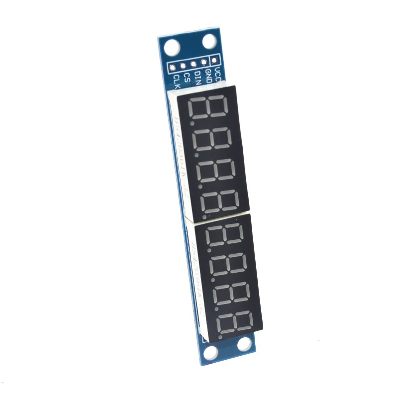
This module solves the common problem of limited I/O pins. With just three connections – DIN (Data In), CLK (Clock), and CS/LOAD (Chip Select) – you can display numbers, letters, and custom characters across all eight digits. The module supports cascading (daisy-chaining) , allowing you to connect multiple modules in series to drive 16, 24, or more digits using the same three control pins .
Whether you are building a digital clock, a temperature display, a counter, a scoreboard, or any project requiring numeric readout, this MAX7219 8-bit LED tube module provides a simple, efficient, and robust solution .
Key Features
-
8-Digit LED Display: Drives up to eight 7-segment LED digits (also supports 8×8 LED matrices and bar-graph displays) .
-
3-Wire Serial Interface: Uses only 3 I/O pins (DIN, CLK, LOAD/CS) to control all 8 digits, freeing up valuable microcontroller pins .
-
High-Speed 10MHz Interface: Enables fast data transmission and real-time display updates without noticeable lag .
-
On-Chip BCD Decoder: Built-in Code B decoder simplifies displaying digits 0-9, with the option to bypass for custom character control .
-
8×8 Static RAM: Internal memory stores each digit’s data, allowing independent updates without rewriting the entire display .
-
16-Step Digital Brightness Control: Software-adjustable brightness from 1/32 to 31/32 of peak current (16 levels) .
-
150µA Low-Power Shutdown Mode: Reduces power consumption when the display is not needed, while retaining data .
-
Display Test Mode: One command lights all segments for quick functionality testing .
-
Cascadable Design: Multiple modules can be daisy-chained to drive 16, 24, or more digits using the same 3 control pins .
-
Wide Operating Voltage: Compatible with 5V systems (Arduino) and 3.3V systems with level shifters .
-
Scan Limit Register: Configurable to display 1 to 8 digits, saving power when fewer digits are needed .
Technical Specifications
| Parameter | Operating Value |
|---|---|
| Driver IC | MAX7219 (Maxim Integrated / Analog Devices) |
| Number of Digits | 8 digits (standard 7-segment) |
| LED Type | Common-Cathode 7-Segment Displays |
| Supply Voltage | 4V – 5.5V DC (5V typical) |
| Operating Current | 8mA – 330mA (dependent on brightness and segments lit) |
| Interface Type | 3-wire serial (DIN, CLK, LOAD/CS) |
| Serial Data Rate | Up to 10 MHz |
| Scanning Rate | 500 Hz – 1300 Hz (automatic multiplexing) |
| On-Chip RAM | 8×8 static RAM (64 bytes) |
| BCD Decoder | Built-in Code B decoder (0-9, E, H, L, P, blank) |
| Brightness Control | 16 steps (software-controlled via intensity register) |
| Shutdown Current | 150 µA (typ.) |
| Segment Current | 40 mA (peak, set by external resistor) |
| Digit Current | 320 mA (peak) |
| Operating Temperature | 0°C to +70°C |
| Module Connector | 5-pin (2.54mm pitch) – VCC, GND, DIN, CS, CLK |
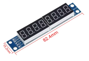
| Dimensions (Typical) | Approx. 50mm × 30mm × 12mm |
Reviews
There are no reviews yet.