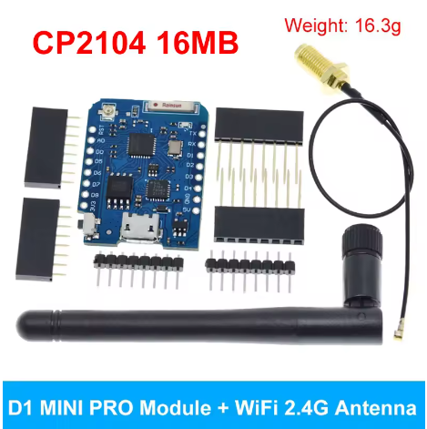
The “Mini D1 PRO NodeMcu Lua WiFi Development Board with Antenna 16MB=128Mbit” refers to an upgraded version of the popular WeMos D1 Mini Pro, featuring the ESP8266 microcontroller, enhanced 16MB (128Mbit) Flash memory, an integrated antenna plus an U.FL connector for an external antenna, and compatibility with Arduino IDE and NodeMCU for IoT projects, offering more storage for complex applications than standard D1 Minis.
Key Features & Specifications:
- Microcontroller: ESP8266EX.
- Flash Memory: 16 Megabytes (128 Megabits).
- Connectivity: 2.4GHz WiFi (802.11b/g/n).
- Antenna: Built-in ceramic antenna and an external U.FL connector.
- Logic Level: 3.3V (higher voltages will damage it).
- Pins: 11 Digital I/O, 1 Analog Input.
- USB-to-UART: CP2104 chip for reliable serial communication.
- Compatibility: Arduino IDE, NodeMCU (Lua), MicroPython.
- Size: Compact (same form factor as the D1 Mini).
What the Name Means:
- Mini D1 PRO: The “PRO” version offers more Flash (16MB vs. 4MB on base D1 Mini) and an external antenna option for better range.
- NodeMcu/Lua: Supports programming with the Lua scripting language via the NodeMCU firmware.
- 16MB=128Mbit: Clarifies that 16 Megabytes of flash storage equals 128 Megabits.
The mini D1 PRO’s combination of powerful Wi-Fi capability and compact size makes it ideal for a wide range of Internet of Things (IoT) projects:
- Smart Home Automation: Control lights, sensors, relays, and other smart devices remotely.
- Remote Sensor Monitoring: Deploy weather stations, soil moisture sensors, or temperature monitors with data logging to cloud platforms (like Thingspeak or MQTT brokers).
- Web Servers: Host simple web interfaces directly on the board to configure settings or display real-time data.
- Robotics & Hobby Projects: Add Wi-Fi capability to small robots or autonomous vehicles for remote control or data transmission.
- Wearable Technology: Its small footprint and Li-Po charging support allow integration into portable, battery-powered projects.
- External Antenna Use Cases: Ideal for projects requiring extended Wi-Fi range or deployment within metal enclosures by using the external antenna connector.
Q: What is the main difference between the standard D1 Mini and the D1 Mini PRO version?
The main differences are enhanced memory and connectivity options. The PRO version typically features:
- More Flash Memory: 16MB (128Mbit) compared to the standard 4MB.
- External Antenna Support: An IPEX/U.FL connector is included for attaching an external 2.4GHz antenna, which improves range and signal stability.
- Battery Charging Circuit: An integrated circuit for charging a connected Lithium Polymer (Li-Po) battery.
Q: What programming environments can I use with this board?
You can program the mini D1 PRO using several popular environments:
- Arduino IDE: The most common choice, using the ESP8266 board manager add-on.
- NodeMCU: Program using Lua scripting language.
- MicroPython: A Python implementation for microcontrollers.
Q: How do I switch between the internal ceramic antenna and the external antenna?
On the D1 Mini Pro board, there is usually a small surface-mount resistor (often marked as a 0 Ohm resistor or a solder jumper) near the IPEX connector. You must physically move this resistor from the “internal antenna” position to the “external antenna” position using a soldering iron. By default, most boards ship configured for the external antenna port.
Q: Can I power the board using a battery?
Yes. The board includes a dedicated JST 2-pin connector for a 3.7V Li-Po battery and an onboard charging circuit. When the micro-USB cable is plugged in, it will power the board and charge the connected battery simultaneously.
Q: Are all GPIO pins 5V tolerant?
No, the ESP8266 chip operates strictly at 3.3V logic levels. Applying 5V directly to any GPIO pin (input or output) may permanently damage the board. You must use a logic level converter when interfacing with 5V components (like standard Arduino shields or sensors).