Product Overview
The Mini MCU2012 TTL Programmer is a compact, high-performance USB-to-TTL serial adapter designed for programming, debugging, and communicating with microcontrollers and embedded systems. Based on the industry-standard Silicon Labs CP2102 chipset, this miniature module creates a virtual COM port on your computer, allowing seamless communication between your PC and UART-enabled devices such as Arduino Pro Mini, ESP8266, ESP32, STM32, and STC microcontrollers .
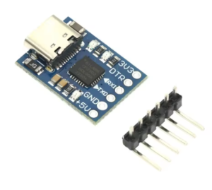
What sets the MCU2012 apart is its incredibly compact form factor and modern connectivity. Measuring just 20mm × 15mm, it is one of the smallest CP2102-based programmers available, making it ideal for space-constrained projects and portable applications . The module features a USB Type-C interface for both power and data connectivity, offering reversible plug orientation, higher durability, and compatibility with modern laptops and devices.
The module retains all essential features including dual 3.3V and 5V power outputs, a self-recovery fuse for short-circuit protection, and full DTR auto-reset support for Arduino-compatible boards . The onboard status LEDs provide real-time visual feedback of power and data transmission activity, simplifying troubleshooting and debugging sessions.
This programmer is particularly well-suited for STC microcontroller development, serving as a reliable downloader for STC series chips, while also functioning as a universal serial adapter for a vast range of other UART devices. The original CP2102 chipset ensures stable operation and broad driver compatibility across Windows, macOS, and Linux platforms .
Key Features
-
Genuine CP2102 Chipset: Based on the original Silicon Labs CP2102 USB 2.0 to UART bridge controller, ensuring stable COM port generation and broad driver compatibility across Windows, macOS, and Linux .
-
USB Type-C Interface: Features a modern USB Type-C connector for both power and data connectivity – reversible plug orientation for easy connection and compatibility with current devices.
-
Ultra-Compact Miniature Design: Extremely small PCB footprint of just 20mm × 15mm, making it perfect for portable projects and integration into tight spaces .
-
Dual Power Output (3.3V & 5V): Provides both 3.3V and 5V switched regulated voltage outputs (common ground) for powering connected target devices .
-
High-Speed Communication: Supports baud rates from 300 bps up to 1 Mbps, suitable for fast firmware uploads and real-time data logging .
-
Built-in Self-Recovery Protection: Integrated resettable fuse protects the USB port and module from damage in case of accidental short circuits .
-
DTR Signal for Auto-Reset: Includes DTR output signal for automatic reset of compatible Arduino and other boards during sketch upload .
-
LED Status Indicators: Provides visual feedback with power and data transmission LEDs – Power (red), TXD (green/blinking), RXD (blue/blinking) .
Technical Specifications
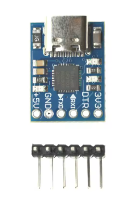
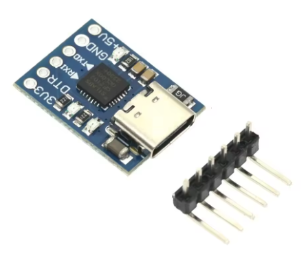
Pinout & Interface Guide
The board features a 6-pin header (2.54mm pitch) labeled as follows:
Important Wiring Note: TXD and RXD are labeled from the CP2102’s perspective:
LED Indicators
Connection Diagrams
Usage Guide
Wiring Instructions
IMPORTANT: Always connect the ground (GND) between the module and your target device first .
Standard Programming Connection (e.g., Arduino Pro Mini)
Basic Serial Communication (No Auto-Reset)
Driver Installation
IMPORTANT: The CP2102 requires driver installation before use. Download the official Silicon Labs CP210x Virtual COM Port (VCP) drivers.
-
Windows: Download from Silicon Labs website. Drivers support Windows 7, 8, 10, and 11.
-
macOS: Official drivers available from Silicon Labs.
-
Linux: Built-in CDC-ACM driver (may work automatically) or download VCP driver .
Driver Installation Notes:
-
After driver installation, the module will appear as a virtual COM port
-
On Windows, check Device Manager → Ports (COM & LPT) for “Silicon Labs CP210x USB to UART Bridge”
-
Note the assigned COM port number for use in your IDE
Testing the Module (Loopback Test)
-
Connect a jumper wire between the TXD and RXD pins .
-
Open a serial terminal program (e.g., Arduino Serial Monitor, PuTTY, CoolTerm).
-
Select the correct COM port and set the baud rate (e.g., 115200).
-
Type characters; they should be echoed back, confirming both transmit and receive paths work.
Application Examples
1. Programming Arduino Pro Mini
Connect the module as shown in the wiring diagram. In the Arduino IDE, select the correct COM port and board (“Arduino Pro or Pro Mini”), then click Upload. The DTR line handles the auto-reset automatically .
2. STC Microcontroller Programming
The MCU2012 serves as an STC microcontroller downloader. Connect TXD→RXD, RXD→TXD, GND→GND, and power the target. Use STC-ISP programming software to flash firmware.
3. Debugging ESP8266 / ESP32
For these 3.3V logic boards, use the 3V3 pin for power. Connect TXD→RX, RXD→TX, and GND→GND. Use a serial monitor to view debug output at appropriate baud rates (e.g., 115200 for normal operation).
Q: What is the difference between this MCU2012 and other CP2102 modules?
The MCU2012 features an ultra-compact 20mm × 15mm footprint – significantly smaller than standard CP2102 modules – while retaining the full feature set and adding a modern USB Type-C connector for reversible plug orientation and better durability.
Q: What microcontrollers can I program with this module?
This module works with virtually any UART-programmable microcontroller, including: Arduino Pro Mini, ESP8266, ESP32, STM32 (“Blue Pill”), STC series microcontrollers, AVR, PIC, and many others
Q: What does the DTR pin do? Why is it important?
The DTR (Data Terminal Ready) pin provides auto-reset functionality. When uploading code to Arduino-compatible boards, DTR automatically resets the microcontroller, eliminating the need to manually time the reset button press .
Q: What is the maximum baud rate supported?
The CP2102 supports baud rates from 300 bps up to 1 Mbps, making it suitable for high-speed data transmission and fast firmware uploads .
Q: Does the module provide both 3.3V and 5V outputs simultaneously?
Yes. Both voltage outputs are available at the same time and share a common ground. This allows you to power devices with different voltage requirements from a single module .
Q: How do I install CP2102 drivers on Windows?
Download the latest “CP210x Universal Windows Driver” from the Silicon Labs website. Run the installer, then connect the module – it should be recognized automatically. Check Device Manager under Ports (COM & LPT) to confirm .
Q: Why can't I upload code to my board?
Follow this checklist:
-
Wiring mismatch: Verify TXD connects to target RX, RXD connects to target TX
-
Driver issues: Ensure CP2102 drivers are properly installed
-
Wrong COM port: Verify correct port selected in IDE
-
Power issues: Ensure target is properly powered
-
Auto-reset: If DTR doesn’t work, manually reset the board during upload
Q: What does the loopback test do, and how do I perform it?
A loopback test verifies the module’s transmit and receive functionality. Short TXD and RXD pins together, open a serial terminal, and type characters – they should echo back. This confirms both communication paths are working correctly .
Q: The module stopped working. What should I check?
The built-in self-recovery fuse may have tripped due to a short circuit . Disconnect the module from USB, wait a few seconds, then reconnect – the fuse will reset automatically.
Q: What is the correct wiring orientation for TXD/RXD?
CP2102 modules use standard labeling where TXD transmits and RXD receives. Connect TXD to target RX, and RXD to target TX . If unsure, swap the two wires – incorrect connection will not damage the devices.
Q: What can I build with this MCU2012 module?
Popular applications include:
-
Programming: Upload firmware to Arduino Pro Mini, ESP8266, ESP32, STM32
-
Debugging: Monitor serial output from any microcontroller
-
PC Interface: Send commands from Python, C# applications to control hardware
-
Data Logging: Receive sensor data for PC visualization
-
GPS Module Interface: Connect GPS modules to computers
-
STC Development: Program STC series microcontrollers
Q: Can this module power my microcontroller project?
Yes, with limits. The 5V output derives directly from USB and is typically limited to about 500mA. This is sufficient for low-power microcontrollers (Arduino Pro Mini, ESP8266 without active Wi-Fi) but not for motors, servos, or high-power components. Use external power for demanding projects.
Q: Is the MCU2012 compatible with STC microcontrollers?
Yes. The MCU2012 is specifically used as an STC programmer downloader. It works with STC-ISP software for program download to STC series microcontrollers.
Q: Does this module work with Raspberry Pi?
Yes. The CP2102 is recognized on Raspberry Pi running Linux. Use it to connect UART devices or as a console debug cable. The device appears as /dev/ttyUSB0 or /dev/ttyACM0 on Linux systems.
Q: What is the 3.3V/5V level compatibility?
The CP2102 operates at 3.3V logic levels internally. When using 5V output, the I/O levels remain at 3.3V, which is compatible with most 5V microcontrollers as they typically recognize 3.3V as logic HIGH. Modern 5V chips (like AVR) officially operate down to 2.7V . Check your target device’s datasheet to verify compatibility – 3.3V is generally safe for 5V tolerant pins.