Description
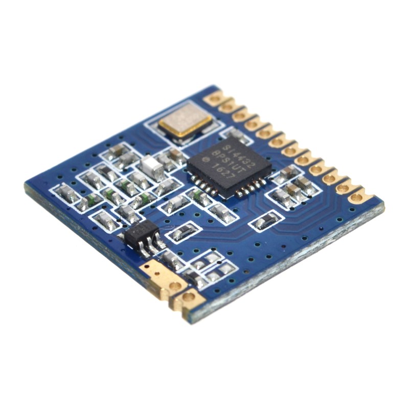
The Mini SI4432 Long-Range Wireless Module is a compact, high-performance RF transceiver module designed for IoT applications, remote control systems, and wireless sensor networks. Built around the Silicon Labs SI4432 transceiver IC – a member of the EZRadioPRO family – this module delivers exceptional range and reliability in a miniature SMD (Surface Mount Device) form factor .
The SI4432 is a highly integrated wireless ISM band transceiver capable of operating across a wide frequency range from 240MHz to 960MHz, with optimized performance in the 410-525MHz band . It features an impressive maximum output power of +20dBm (100mW) and outstanding receiver sensitivity of -117dBm to -121dBm, enabling open-area communication distances of over 1000 meters .
This module is designed for developers who need reliable long-range wireless communication without extensive RF engineering knowledge. The SI4432 handles all RF modulation and demodulation tasks, including FSK, GFSK, and OOK modulation schemes, with data rates ranging from 0.123kbps to 256kbps . The module communicates with your host microcontroller via a standard SPI interface, requiring only 4-5 I/O pins for full control.
Key integrated features include a 64-byte FIFO for buffering transmit and receive data, digital RSSI for signal strength monitoring, automatic CRC calculation and checking, programmable packet handling, and low battery detection . The chip also includes an integrated temperature sensor and 8-bit ADC for environmental monitoring applications.
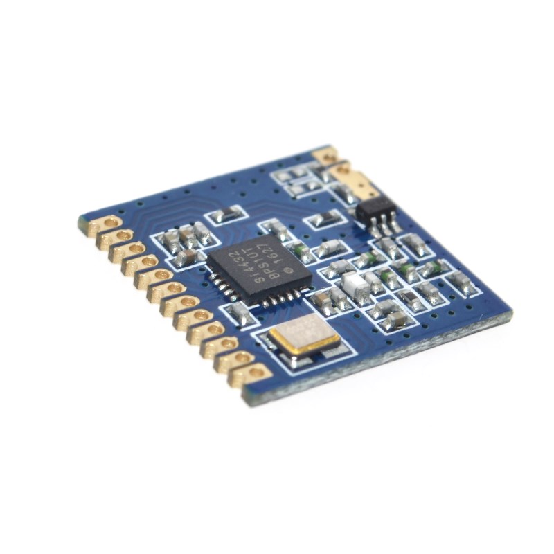
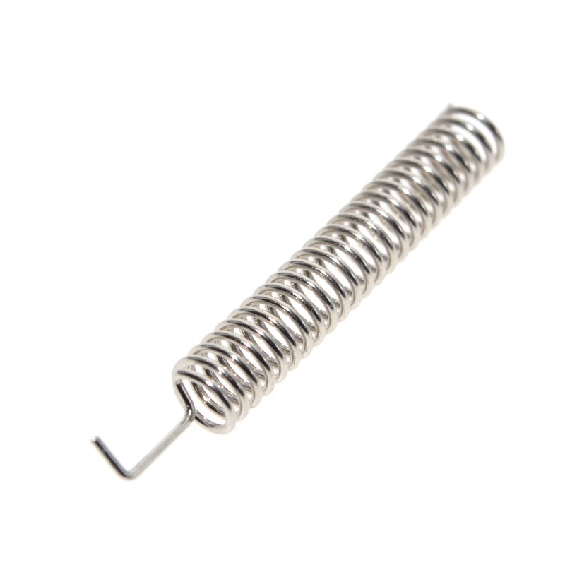
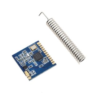
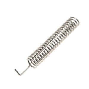
The module’s SMD (stamp-hole) design allows for direct surface-mount soldering onto custom PCBs, making it ideal for volume production and space-constrained applications. A spring antenna is included with each module for immediate out-of-box use.
Whether you need to build a long-range remote control system, a wireless sensor network for agriculture or industrial monitoring, a remote meter reading system, or a wireless alarm system, the Mini SI4432 module delivers reliable, high-performance wireless communication in a miniature package .
Key Features
-
Ultra-Long Range – Up to 1000+ meters open-area communication distance with +20dBm output power and -121dBm sensitivity
-
Wide Frequency Range – Operates from 240MHz to 960MHz (optimized for 410-525MHz, including 433MHz ISM band)
-
High Output Power – Maximum +20dBm (100mW) transmit power with 8 adjustable power levels
-
Multiple Modulation Schemes – Supports FSK, GFSK, and OOK modulation for flexible application use
-
Low Power Consumption – Receive current: 18.5mA; Standby current: 300nA; Shutdown current: 10nA
-
SPI Control Interface – Simple 4-wire SPI connection to any microcontroller (Arduino, ESP32, STM32, etc.)
-
Integrated Features – 64-byte FIFO, digital RSSI, temperature sensor, 8-bit ADC, low battery detection
-
Miniature SMD Package – Compact dimensions (approx. 17×16.5mm) with stamp-hole pads for PCB integration
-
Wide Supply Voltage – Operates from 1.8V to 3.6V DC (3.3V recommended)
-
Industrial Temperature Range – -40°C to +85°C for reliable outdoor and industrial use
Technical Parameters
Usage Guide
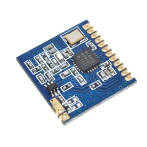
Hardware Overview
The Mini SI4432 module is based on the Silicon Labs SI4432 B1 revision transceiver IC . The module includes all necessary RF matching components, a crystal oscillator, and a spring antenna. The compact SMD design features stamp-hole pads for direct PCB soldering.
Key Components:
-
SI4432 Transceiver IC – Handles all RF modulation/demodulation
-
Crystal Oscillator – High-precision 10ppm crystal
-
Spring Antenna – Included, tuned for 433MHz operation
-
RF Matching Network – High-frequency Murata inductors and capacitors
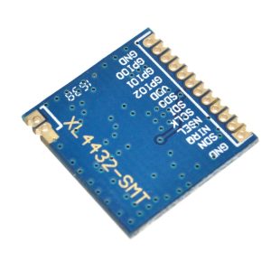
Pinout Description
The module uses a stamp-hole SMD interface (typical 10-12 pins depending on manufacturer). The key pins for operation are:
⚠️ IMPORTANT – Voltage Level Warning: The SI4432 is NOT 5V tolerant. All I/O pins operate at 3.3V logic levels. When connecting to 5V microcontrollers (e.g., Arduino Uno), you MUST use a level shifter on all SPI lines (SCK, MOSI, MISO, nSEL) to avoid permanent damage to the module .
Wiring Instructions
To 3.3V Microcontrollers (ESP32, ESP8266, STM32, Raspberry Pi, 3.3V Arduino Pro Mini):
To 5V Microcontrollers (Arduino Uno/Mega) – WITH Level Shifter Required:
Power Supply Considerations:
-
The SI4432 requires up to 80mA during transmit and 18.5mA during receive
-
For reliable operation, use a dedicated 3.3V regulator capable of supplying at least 200mA
-
Do not power from a microcontroller’s 3.3V pin alone, as many boards cannot supply sufficient current
-
Add a 10µF and 0.1µF decoupling capacitor near the module VCC pin
Antenna Installation
-
Solder the included spring antenna to the designated ANT pad on the module
-
For maximum range, keep the antenna straight and vertical
-
Keep the antenna away from metal surfaces and ground planes
-
For metal enclosures, use an external antenna with an SMA connector and feedline
-
A simple 17-23cm straight copper wire can be used as an alternative antenna
Software Setup – Arduino
Required Libraries:
Two popular options for Arduino are:
-
RadioLib – Comprehensive library supporting many RF modules including Si4432
-
Arduino-SI4432 – Dedicated library for Si443x series
Installing RadioLib (Recommended):
-
Open Arduino IDE → Tools → Manage Libraries
-
Search for “RadioLib”
-
Install by jgromes
Basic Transmit Example (RadioLib):
#include <RadioLib.h>
Si4432 radio = new Module(10, 2, 9);
void setup() {
Serial.begin(9600);
Serial.print(F("[SI4432] Initializing..."));
int state = radio.begin();
if (state == RADIOLIB_ERR_NONE) {
Serial.println(F("success!"));
} else {
Serial.print(F("failed, code "));
Serial.println(state);
while (true);
}
state = radio.setFrequency(433.0);
state = radio.setOutputPower(20);
state = radio.setBitRate(9.6);
Serial.println(F("Ready to transmit"));
}
void loop() {
String message = "Hello from SI4432!";
Serial.print(F("[SI4432] Sending packet ... "));
int state = radio.transmit(message);
if (state == RADIOLIB_ERR_NONE) {
Serial.println(F("success!"));
} else {
Serial.print(F("failed, code "));
Serial.println(state);
}
delay(2000);
}
Basic Receive Example (RadioLib with Interrupts):
#include <RadioLib.h>
Si4432 radio = new Module(10, 2, 9);
volatile bool receivedFlag = false;
void setFlag(void) {
receivedFlag = true;
}
void setup() {
Serial.begin(9600);
int state = radio.begin();
radio.setFrequency(433.0);
radio.setBitRate(9.6);
radio.setIrqAction(setFlag);
state = radio.startReceive();
Serial.println(F("Listening for packets..."));
}
void loop() {
if (receivedFlag) {
receivedFlag = false;
String received;
int state = radio.readData(received);
if (state == RADIOLIB_ERR_NONE) {
Serial.print(F("Received: "));
Serial.println(received);
} else if (state == RADIOLIB_ERR_CRC_MISMATCH) {
Serial.println(F("CRC error!"));
}
radio.startReceive();
}
}
Antenna and Layout Design Considerations
For optimal performance, follow these PCB layout guidelines :
-
Keep antenna area clear – No copper fill or components under/around the antenna
-
Use high-quality RF components – Murata or similar high-Q capacitors/inductors
-
Maintain spacing – Keep 0.5mm minimum clearance between RF traces and ground fill
-
Add ground vias – Place multiple vias around RF sections for isolation
-
Use thin PCB – 0.8-1.0mm board thickness recommended for RF performance
Range Optimization Tips
-
Use lower data rates – 1.2kbps provides maximum sensitivity (-121dBm)
-
Set maximum transmit power – +20dBm output
-
Ensure proper antenna tuning – Spring antenna should be straight and vertical
-
Maintain line of sight – Clear path between transmitter and receiver
-
Use external antenna for metal enclosures – Signals are blocked by metal
-
Add error detection – Implement CRC or packet retry mechanisms
-
Avoid interference – Select a clear channel in your frequency band
Typical Applications
Q: What is the maximum range of this SI4432 module?
The module can achieve over 1000 meters (1 kilometer) in open areas with clear line of sight, using the included spring antenna, maximum transmit power (+20dBm), and low data rates (1.2kbps) . Actual range varies based on environmental factors, antenna quality, and interference.
Q: Can I use this module with a 5V Arduino (Uno, Mega)?
Yes, but you MUST use a level shifter. The SI4432 is NOT 5V tolerant – all I/O pins operate at 3.3V logic levels . You need a 4-channel bi-directional level shifter for the SPI lines (SCK, MOSI, MISO, nSEL). The module’s VCC should be powered from a 3.3V regulator, not directly from the Arduino’s 5V pin.
Q: What is the operating frequency range?
The SI4432 can operate from 240MHz to 960MHz, with optimized matching for the 410-525MHz range . The included spring antenna is tuned for 433MHz (ISM band). For other frequencies, you may need a different antenna.
Q: What is the difference between FSK, GFSK, and OOK modulation?
-
FSK (Frequency Shift Keying) – Standard modulation; good balance of range and data rate
-
GFSK (Gaussian FSK) – Smoother frequency transitions; reduced spectral bandwidth
-
OOK (On-Off Keying) – Simpler modulation; carrier ON = 1, OFF = 0; used in basic remote controls
All three are supported by the SI4432 . For most applications, GFSK is recommended for its spectral efficiency.
Q: How do I control the module without a library?
The SI4432 uses a SPI interface. You will need to:
-
Configure the chip by writing to its configuration registers (74+ registers)
-
Set up transmit/receive modes via the API
-
Manage the 64-byte FIFO for data buffering
Using an existing library (RadioLib or Arduino-SI4432) is strongly recommended for beginners
Q: What is the current consumption?
| Mode |
Typical Current |
| Transmit (+20dBm) |
~80mA (max) |
| Receive |
18.5mA |
| Standby |
300nA |
| Shutdown (SDN pin HIGH) |
10nA |
Q: Why is my module not communicating?
Troubleshooting steps:
-
Check voltage – Ensure 3.3V supply (1.8-3.6V range). Do not exceed 3.6V.
-
Check level shifting – If using 5V microcontroller, verify level shifter connections
-
Verify antenna – Ensure spring antenna is soldered and straight
-
Check SPI connections – Confirm SCK, MOSI, MISO, nSEL wiring
-
Power supply – Add 10µF decoupling capacitor near VCC pin
-
Module separation – Start with 5-10 meters distance (too close can overload receiver)
Q: Can I use this module for both home and business applications?
Home users: Long-range remote controls, DIY weather stations, garden irrigation control, garage door openers, wireless sensor networks.
Business users: Industrial telemetry, remote equipment monitoring, agricultural sensor networks (greenhouse monitoring) , wireless alarm systems, remote meter reading, asset tracking
Q: Is the module compatible with other SI4432 modules from different manufacturers?
Yes. All SI4432-based modules using the same frequency, modulation, and data rate settings should be compatible. The SI4432 is a standard chip from Silicon Labs, and modules from different manufacturers using this chip should interoperate when configured identically.
Q: What is the SDN pin for?
The SDN (Shutdown) pin is an active-high shutdown control. When pulled HIGH:
-
The entire chip is powered down
-
Current consumption drops to 10nA
-
Configuration is lost and must be re-initialized on wake-up
For normal operation, keep SDN LOW (connected to GND) . This pin is useful for ultra-low-power battery applications where the module is only active occasionally.