Product Overview
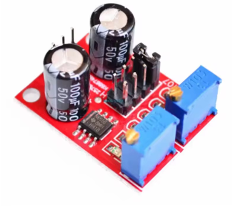
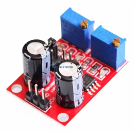
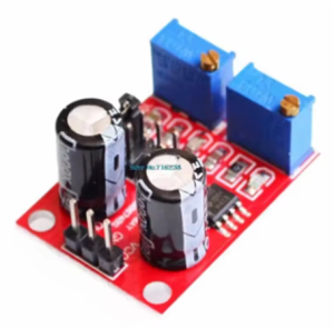
The NE555 Pulse Frequency Duty Cycle Adjustable Module is a compact, versatile signal generator built around the legendary NE555 timer IC – one of the most popular and reliable integrated circuits in history. This module generates stable square wave and rectangular wave signals with independently adjustable frequency and duty cycle, making it an indispensable tool for electronics experimentation, stepper motor control, and PWM (Pulse Width Modulation) applications .
Unlike basic fixed-frequency oscillators, this module gives you fine-grained control over both the signal’s speed (frequency) and its on/off ratio (duty cycle). Whether you need a low-frequency pulse for a flashing LED, a mid-range signal for driving a stepper motor driver, or a high-frequency clock for testing digital circuits, this module delivers.
At its core is the NE555 timer, operating in astable (free-running) mode. The module features a multi-range frequency selector and two precision potentiometers, allowing you to adjust the output from as low as 1Hz up to 200kHz, and the duty cycle from approximately 5% to 95% .
An onboard LED indicator provides real-time visual feedback: it lights up when the output is low, turns off when the output is high, and flashes visibly at lower frequencies – perfect for quick diagnostics without an oscilloscope .
Key Features
-
Wide Frequency Range: Selectable from four ranges covering 1Hz to 200kHz, from slow pulses for visual indicators to high-speed signals for digital circuits .
-
Adjustable Duty Cycle: Fine-tune the pulse width (on/off ratio) from approximately 5% to 95% via onboard potentiometer, essential for PWM motor speed control and servo positioning .
-
Multi-Range Frequency Selection: Four jumper-selectable frequency ranges allow continuous adjustment across decades:
-
Low Frequency (LF): 1Hz – 50Hz (timing capacitor C = 0.001µF)
-
Medium Frequency (MF): 50Hz – 1kHz (C = 0.01µF)
-
High Frequency (HF): 1kHz – 10kHz (C = 0.1µF)
-
Ultra High Frequency (UHF): 10kHz – 200kHz (C = 10µF-100µF)
-
Wide Operating Voltage: Accepts 5V to 15V DC power input, compatible with both 5V (Arduino, ESP32) and 12V (industrial, automotive) systems .
-
LED Output Indicator: Built-in LED provides visual confirmation of output activity – lights on low level, off on high level, flashes visibly at low frequencies .
-
Compact Form Factor: Small PCB size (approx. 31mm × 22mm), easily integrated into breadboards, enclosures, or permanent projects .
-
Versatile Signal Levels: Output amplitude ranges from 4.2Vpp at 5V input to 11.4Vpp at 12V input, with output current of 15-35mA depending on supply voltage .
Technical Specifications
Pinout & Configuration Guide
Power Terminals
Output Terminal
Frequency Range Selection Jumpers (FD – Frequency Divider)
The module uses 2-pin jumpers (FD1, FD2, etc.) to select the frequency range. The jumper placement selects different timing capacitors:
Only ONE jumper should be placed at a time.
Adjustment Controls
Usage Guide
Stepper Motor Drive Application
This module is excellent for generating the pulse signal (STEP input) required by stepper motor drivers. Connect the OUT pin to the STEP input of your stepper driver (e.g., TB6600, A4988). The frequency determines the motor speed; the duty cycle is typically set to 50% for best performance .
Wiring Example:
Module OUT → Stepper Driver STEP input
Module GND → Stepper Driver GND (common ground)
Module VCC → 5V or 12V supply
Stepper Driver → Stepper Motor + Power
PWM Signal Generation
For PWM applications (LED dimming, motor speed control), set the frequency to the desired range (e.g., 1kHz-10kHz for audible applications) and use the duty cycle potentiometer to control the average power delivered to the load .
Arduino / MCU Clock Source
Generate an adjustable clock signal for microcontroller projects. The module can serve as an external clock source for timing experiments, pulse counting, or synchronizing multiple devices .
Circuit Testing & Experimentation
Use this module as a standalone signal source for testing digital circuits, amplifiers, filters, and other electronics projects. The wide frequency range and adjustable duty cycle make it a versatile benchtop tool .
Important Usage Notes
-
Duty Cycle vs. Frequency Interaction: Adjusting the duty cycle potentiometer will cause the frequency to change slightly. This is a known characteristic of the NE555 astable configuration . For applications requiring independent control, consider using a dedicated PWM generator.
-
Minimum Frequency for LED Visibility: At very low frequencies, the output LED will visibly flash, confirming the output is active. This is normal and helpful for troubleshooting .
-
Output Current Limitation: The module’s output current is limited to 15-35mA. Do not connect directly to high-current loads (e.g., motors) – use a driver circuit or transistor buffer .
-
Stepper Motor Drive: This module generates the control signal (STEP pulse). You still need a separate stepper motor driver (e.g., TB6600, A4988, DRV8825) between this module and the actual stepper motor .
Q: What is the difference between frequency and duty cycle?
Frequency is how many pulses occur per second (Hz). Duty cycle is the percentage of time the signal is HIGH (on) vs. LOW (off) within each pulse period. A 50% duty cycle means the signal is HIGH half the time and LOW half the time; a 30% duty cycle means it’s HIGH 30% of the period and LOW 70% .
Q: Can this module drive a stepper motor directly?
No. This module generates the control signal (square wave pulses) needed by a stepper motor driver. The output current is limited to ~35mA, which is insufficient to directly power a stepper motor winding. You must connect this module’s output to a dedicated stepper motor driver (e.g., TB6600, A4988, DRV8825), which then powers the motor .
Q: What is the output voltage amplitude?
The output amplitude depends on the supply voltage:
The output is compatible with 5V TTL logic (Arduino, ESP32) when powered by 5V, and with 12V industrial systems when powered by 12V .
Q: Why does the LED flash at low frequencies?
The LED is connected to the output signal. It lights up when the output is LOW and turns off when the output is HIGH. At low frequencies (e.g., 1-5Hz), you can see the LED physically flashing. At higher frequencies, it appears constantly lit due to persistence of vision. This is normal and helpful for confirming output activity .
Q: How do I select the correct frequency range?
Start with the lowest range (1Hz-50Hz) and adjust the frequency potentiometer. If you need higher frequencies, move the jumper to the next range. Only one jumper should be installed at a time. The four ranges are :
-
LF (1Hz-50Hz): Slow timing, visual indicators
-
MF (50Hz-1kHz): Audio, basic motor pulses
-
HF (1kHz-10kHz): Stepper motor drive, PWM
-
UHF (10kHz-200kHz): High-speed clocks
Q: Does adjusting duty cycle affect frequency?
Yes. Due to the NE555 astable circuit design, adjusting the duty cycle potentiometer will cause the frequency to change slightly. These parameters are not independently adjustable on this module. For applications requiring strict independent control, a dedicated PWM generator module is recommended .
Q: What is the formula for calculating the frequency?
The frequency is determined by: T = 0.7 × (RA + 2RB) × C
Where:
-
T = Period (seconds)
-
RA = Frequency potentiometer resistance (0-10kΩ)
-
RB = Duty cycle potentiometer resistance (0-10kΩ)
-
C = Timing capacitor value (selected by range jumper)
Frequency = 1 / T .
Q: Can I use this module with a 3.3V microcontroller?
This module requires a minimum of 5V for reliable operation (the NE555 is specified down to 4.5V). For 3.3V systems, you have two options: power the module from a separate 5V supply and use a level shifter on the output, or use a 5V-to-3.3V voltage divider on the output pin before connecting to your 3.3V device.
Q: What are the power supply requirements?
The module accepts 5V to 15V DC. Ensure your power supply can deliver at least 100mA. Both 5V (Arduino, USB) and 12V (automotive, industrial) are acceptable. Higher voltage yields higher output amplitude .
Q: How do I know which jumper corresponds to which frequency range?
The PCB is typically marked with “FD” (Frequency Divider) labels. Consult your specific module’s silkscreen or included documentation. The general mapping is:
-
FD1 / LF / C=0.001µF: 1Hz-50Hz
-
FD2 / MF / C=0.01µF: 50Hz-1kHz
-
FD3 / HF / C=0.1µF: 1kHz-10kHz
-
FD4 / UHF / C=1-100µF: 10kHz-200kHz .
Q: Can I use this module as a PWM speed controller for a DC motor?
Yes, but with a transistor or MOSFET driver. The module’s output current is limited to 15-35mA, which is insufficient to directly power a motor. Connect the module’s output to the gate/base of a power transistor or MOSFET, which then switches the motor’s power supply. This configuration is ideal for PWM speed control .
Q: What is the maximum output frequency?
The maximum frequency is approximately 200kHz in the highest frequency range (UHF). At very high frequencies, the output waveform may become less perfect due to the NE555’s slew rate limitations, but it remains suitable for most digital and clock applications .