Product Overview
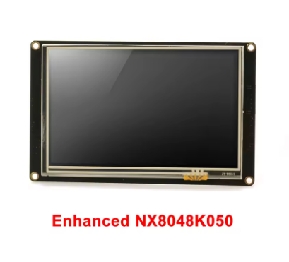
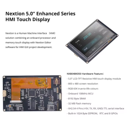
The Nextion Enhanced NX8048K050 is a powerful, intelligent Human-Machine Interface (HMI) display module that integrates a 5.0-inch TFT LCD color screen with a resistive touch panel into a single, ready-to-use package. Designed to provide a seamless control and visualization interface between humans and machines, this Enhanced series display is the ideal solution for IoT applications, consumer electronics, industrial automation, and embedded projects.
What sets the Nextion apart from traditional LCDs is its intelligent architecture. Unlike standard displays that require your main microcontroller to handle all graphics rendering, the NX8048K050 features a dedicated onboard processor that independently manages all graphical interface functions—drawing buttons, updating text, displaying graphs, processing touch inputs, and managing screen transitions. Your host microcontroller (Arduino, ESP32, Raspberry Pi, STM32) communicates with the display using simple ASCII text commands over a standard UART (TTL serial) interface. This approach eliminates the need for complex graphics programming and parallel wiring, dramatically reducing development time.
The Enhanced series (NX8048K050) represents a significant upgrade over the Basic series (NX8048T050). Enhancements include a faster CPU clock, built-in Real-Time Clock (RTC), 32MB flash memory (vs 16MB), 8192 bytes of RAM (vs 3584 bytes), 1024 bytes of EEPROM for user data storage, and 8 digital GPIO pins (with 4 supporting PWM). This makes the Enhanced series suitable for standalone applications that require local data storage, timekeeping, and external device control without an additional microcontroller.
Key Features
-
5.0-Inch TFT LCD Display: 800 × 480 pixel resolution with 65,536 colors (16-bit RGB 565), providing vivid, true-to-life visuals at 230 nits brightness
-
Resistive Touch Panel: Durable 4-wire resistive touch screen rated for over 1 million touches; responds to finger, gloved hand, or stylus input
-
Enhanced Series Advantages: Compared to Basic models, features faster MCU clock (108MHz), built-in RTC with CR1220 battery backup, 32MB flash, 8192 bytes RAM, 1024 bytes EEPROM, and 8 GPIO pins (4 PWM capable)
-
Simple Serial Communication: 4-pin UART interface (VCC, GND, TX, RX) using TTL 3.3V/5V tolerant logic—connects directly to Arduino, ESP32, Raspberry Pi, or STM32
-
Intelligent Standalone Operation: Onboard processor handles all graphics and touch processing independently—your host MCU only needs to send simple commands
-
Free WYSIWYG GUI Editor: Nextion Editor software with drag-and-drop components (buttons, text boxes, sliders, progress bars, gauges) and built-in simulator for debugging without hardware
-
Adjustable LED Backlight: Brightness adjustable from 0% to 230 nits in 1% increments via simple serial command
-
Built-in RTC (Real-Time Clock): Maintains accurate time even when main power is off with CR1220 backup battery (sold separately)
-
Expandable GPIO: 8 digital GPIO pins (IO0-IO7) for controlling external devices directly from the HMI; IO4-IO7 support PWM output
-
microSD Card Slot: For firmware updates (TFT file upload). Supports FAT32 format, up to 32GB
Technical Specifications
Pinout & Connection Guide
The module uses a simple 4-pin, 2.54mm pitch header for all communication and power. The pinout is clearly marked on the back of the PCB.
Pin Definitions
Wiring Diagrams
Arduino Uno / Mega (5V logic):
NX8048K050              →    Arduino Uno
──────────────────────────────────────────────
VCC                     →    5V
TXD                     →    RX (Pin 0)
RXD                     →    TX (Pin 1)
GND                     →    GND
ESP32 (3.3V logic):
NX8048K050              →    ESP32
──────────────────────────────────────────────
VCC                     →    External 5V Supply (not from ESP32)
TXD                     →    GPIO16 (RX2)
RXD                     →    GPIO17 (TX2)
GND                     →    GND
Raspberry Pi:
NX8048K050              →    Raspberry Pi
──────────────────────────────────────────────
VCC                     →    Pin 2 (5V) or external 5V supply
TXD                     →    Pin 10 (RXD / GPIO15)
RXD                     →    Pin 8 (TXD / GPIO14)
GND                     →    Pin 6 (GND)
Note: The Nextion requires a stable 5V supply capable of delivering at least 1A. The package includes a power supply test board to verify your power source is adequate before connecting the display.
Development & Usage Guide
1. Nextion Editor Software
Design your HMI interface using the free Nextion Editor software, available for download from the official Nextion website. The software features:
-
Drag-and-Drop Components: 25+ built-in components including buttons, text boxes, sliders, progress bars, gauges, timers, and more
-
WYSIWYG Interface: See exactly how your GUI will look while you design it
-
Free Simulator: Debug your HMI project without hardware—test interactions and commands in real-time
-
Font Creator: Generate custom fonts with specific encoding (UTF-8 support for international characters)
2. Creating Your First HMI Project
Basic Workflow:
-
Launch Nextion Editor and click “New”
-
Select “Enhanced” as the series and choose “NX8048K050” as the model
-
Drag components from the toolbox onto the page canvas
-
Configure component properties (colors, text, size, position, etc.)
-
For interactive components, enable “Send Component ID” in the Event pane to allow your host MCU to detect touch events
-
Set communication baud rate—add bauds=115200 (or your desired rate) to the Preinitialize Event of the first page
-
Press F8 to compile the project and generate a .tft firmware file
3. Uploading Firmware to the Display
Recommended Method: microSD Card
-
Format a microSD card as FAT32 (maximum 32GB)
-
Copy the compiled .tft file to the root directory of the SD card
-
Ensure the card contains only one .tft file
-
Power off the Nextion display
-
Insert the microSD card into the display’s slot
-
Power on the display—firmware uploads automatically
-
After “Update Success!” message appears, power off
-
Remove the microSD card before powering on again
4. Power Supply Considerations
Critical Power Requirements:
-
The NX8048K050 requires a stable 5V DC power supply capable of delivering at least 1A
-
Operating current is 410mA at 100% brightness, with higher peaks during startup
-
Do not power the display from your microcontroller’s 3.3V pin
-
The included power test board allows you to verify your power supply can meet the requirements
5. Host MCU Communication (Arduino Example)
Once your GUI is loaded, control the display from your microcontroller using simple print statements. Important: Every command sent to the Nextion must end with three bytes of 0xFF (the command terminator).
void setup() {
Serial.begin(115200);
delay(3000);
}
void loop() {
Serial.print("t0.txt=\"Hello World\"");
Serial.write(0xFF); Serial.write(0xFF); Serial.write(0xFF);
delay(2000);
static int counter = 0;
counter++;
Serial.print("n0.val=");
Serial.print(counter);
Serial.write(0xFF); Serial.write(0xFF); Serial.write(0xFF);
delay(1000);
}
6. Using the Iteadlib Arduino Library
The ITEADLIB_Arduino_Nextion library simplifies communication by handling the 0xFF terminators automatically.
Installation:
-
Download the library ZIP from GitHub
-
In Arduino IDE: Sketch → Include Library → Add .ZIP Library
Basic Library Example:
#include "Nextion.h"
NexText t0 = NexText(0, 1, "t0");
NexNumber n0 = NexNumber(0, 2, "n0");
void setup() {
nexInit();
}
void loop() {
t0.setText("Hello");
n0.setValue(42);
delay(1000);
}
7. ESP32 Setup Notes
When using the ESP32, configure the library for hardware Serial2:
In NexConfig.h, modify:
#define nexSerial Serial2
Additionally, comment out #include <SoftwareSerial.h> and the NexUpload files as SoftwareSerial is incompatible with the ESP32.
8. RTC Battery Installation
The Enhanced series includes a built-in Real-Time Clock. To keep time when main power is off:
9. GPIO Usage
The NX8048K050 provides 8 digital GPIO pins (IO0-IO7) that can be used as:
-
Digital inputs: Read external sensor states
-
Digital outputs: Control external devices (limit current to 1mA recommended)
-
PWM outputs: IO4-IO7 support PWM for dimming LEDs or controlling servos
These GPIOs can be controlled directly from the Nextion Editor using component events, without involving your host MCU.
Q: What is the difference between NX8048K050 (Enhanced) and NX8048T050 (Basic)?
The Enhanced series (NX8048K050) adds several powerful features: a faster 108MHz MCU clock (vs 48MHz), built-in Real-Time Clock (RTC) with battery backup, 32MB flash memory (vs 16MB), 8192 bytes of RAM (vs 3584 bytes), 1024 bytes of EEPROM for user data storage, and 8 digital GPIO pins (4 with PWM capability). The Basic series is suitable for standard HMI applications, while the Enhanced series is ideal for standalone applications requiring local data storage, timekeeping, and external device control.
Q: Can I use this display with a 3.3V logic microcontroller like ESP32 without a level shifter?
Yes, with proper power separation. The Nextion’s RXD pin is 5V tolerant and accepts 3.3V logic signals from the ESP32. The TXD pin outputs 3.3V logic, which is compatible with the ESP32’s input levels. However, the VCC pin must be powered by a separate 5V supply capable of delivering at least 1A. Do not attempt to power the display from your microcontroller’s 3.3V pin.
Q: Why is my display not responding to commands?
Check these common issues:
-
No firmware loaded: The display must have a valid .tft file flashed
-
Incorrect command termination: Every command must end with three bytes of 0xFF
-
Baud rate mismatch: The default baud rate is 9600; ensure your code matches
-
Power supply: Ensure your 5V power supply can deliver at least 1A
-
**Correct COM port and baud rate in your serial monitor software
Q: How do I change the baud rate of the Nextion display?
In your Nextion Editor project, add the command bauds=115200 (or your desired rate—up to 921600 bps) to the Preinitialize Event of your first page. This sets the communication speed when the display boots. Remember to also change your microcontroller’s Serial port baud rate to match.
Q: What is the microSD card used for?
The microSD card slot is exclusively for upgrading the Nextion’s firmware (uploading your .tft GUI file). The display cannot read files from the SD card during normal operation—it is for programming only. Use FAT32 format, maximum 32GB, and ensure only one .tft file is present
Q: Can the Nextion display operate without a host microcontroller?
Yes, to a limited extent. The Nextion Enhanced series can run simple logic using its onboard processor, GPIO, timers, and RTC. However, for most IoT and complex control applications, it acts as a slave device, with an external MCU sending commands and receiving touch events. The Nextion handles the user interface; the MCU handles the application logic.
Q: How do I detect button presses on the Nextion?
In the Nextion Editor, select your button component. In the Event pane, check the “Send Component ID” checkbox for the “Push” or “Release” event. Your microcontroller will receive a code (e.g., 65 0 1 for button 1 on page 0) when the button is touched.
Q: What is the purpose of the included power supply test board?
The power supply test board allows you to verify your power source can deliver adequate current before connecting the display. Insufficient power is a common cause of Nextion damage and erratic behavior. Test your power source with the included test board first.
Q: Why is my display flickering or showing corrupt graphics?
This is almost always a power supply issue. The NX8048K050 draws about 410mA at 100% brightness, with higher current spikes during startup. Ensure your power supply provides a stable 5V at 1A. Check that VCC and GND wires are securely connected and use adequate wire gauge.
Q: Can I use multiple Nextion displays with one microcontroller?
Yes, but each display requires its own UART port. Since each Nextion has its own addressable component IDs, you can send commands to specific displays using their dedicated serial connections. However, you cannot share a single UART between multiple displays—each needs a unique serial port on your microcontroller.
Q: What is the purpose of the CR1220 battery? Is it required?
The CR1220 battery socket is for the built-in Real-Time Clock (RTC). The battery maintains accurate time when the main power to the display is turned off. The battery does NOT power the display itself—if you don’t need timekeeping functionality, you can leave the battery slot empty.
Q: Does the Nextion display support touch sounds or haptic feedback?
The Nextion display itself does not have built-in speakers or vibration motors for audio/tactile feedback. However, you can implement these features externally—your host microcontroller can be programmed to trigger a buzzer or vibration motor when it receives a touch event code from the display.