Product Overview
The Onboard CP2102 USB Type-C Serial Converter Module is a high-performance, single-chip USB-to-UART bridge solution designed to provide seamless serial communication between your computer’s modern USB Type-C port and microcontroller-based embedded systems. Based on the industry-standard Silicon Labs CP2102 controller , this module creates a virtual COM port on your computer, allowing you to program, debug, and communicate with a wide range of devices including Arduino, ESP8266, ESP32, STM32, and STC microcontrollers.
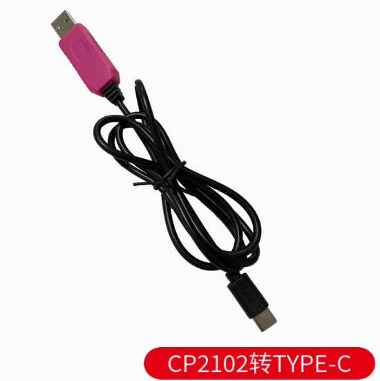
The module features the modern USB Type-C connector, offering reversible plug orientation and compatibility with the latest laptops, tablets, and smartphones. Unlike older USB-A adapters, the Type-C interface is future-proof and eliminates the frustration of plugging in the cable the wrong way.
At the heart of this module is the CP2102 chip, which integrates a USB 2.0 full-speed function controller, USB transceiver, oscillator, and EEPROM—all in a compact package, requiring no external resistors or crystal . The module provides both 3.3V and 5V logic level support, selectable via onboard jumper, making it compatible with virtually any target device voltage requirement . Whether you’re flashing firmware onto a router, accessing a Raspberry Pi console, or debugging sensor data, this adapter delivers reliable, high-speed communication with baud rates up to 1 Mbps.
Key Features
-
Genuine Silicon Labs CP2102 Chipset: High-performance USB-to-UART bridge controller, ensuring excellent stability and broad driver compatibility .
-
USB Type-C Interface: Modern reversible connector for easy plug-in orientation; compatible with the latest laptops, smartphones, and tablets .
-
Dual Voltage Output (3.3V/5V): Selectable output voltage via onboard jumper to match your target device’s logic level—supports both 3.3V and 5V systems .
-
High-Speed Data Transfer: Supports baud rates from 300 bps up to 1 Mbps, suitable for fast firmware uploads and real-time debugging .
-
Integrated 1024-byte EEPROM: Programmable memory for customizing USB configuration parameters (VID, PID, serial number, product description strings) .
-
Full Handshake Support: Provides complete modem control signals (RTS, CTS, DTR, DSR, DCD, RI) for hardware flow control .
-
Onboard Status LEDs: POWER, TXD, and RXD LEDs provide real-time visual feedback of power and data transmission activity .
-
Self-Recovery Fuse: Integrated protection circuitry safeguards your computer’s USB port from accidental short circuits or overcurrent conditions .
-
Built-in Voltage Regulator: On-chip 3.3V voltage regulator eliminates the need for external power components .
-
Plug-and-Play Driver Support: Compatible with Windows 7/8/10/11, macOS, Linux, and Android—virtual COM port drivers available for all major operating systems .
Technical Specifications
Pinout & Connection Guide
The module features a 6-pin header (2.54mm pitch) with clearly labeled pins on the PCB silkscreen:
Jumper Configuration for Voltage Selection:
Important Connection Notes:
-
The TXD pin of the module must connect to the RX pin of your target device
-
The RXD pin of the module must connect to the TX pin of your target device
-
Always establish a common ground by connecting the GND pin
-
Select the correct voltage output jumper before connecting to your target device to prevent damage
Usage Guide
Driver Installation
The CP2102 chip requires Virtual COM Port (VCP) drivers for operation .
Windows 7/8/10/11:
-
Download the latest CP210x Universal Windows Driver from the Silicon Labs website
-
Run the installer (CP210xVCPInstaller_x64.exe for 64-bit systems)
-
Connect the Type-C adapter to your computer
-
Verify installation in Device Manager → Ports (COM & LPT) → “Silicon Labs CP210x USB to UART Bridge”
*Note: Windows 10/11 may automatically install the driver via Windows Update* .
macOS:
-
Download the CP210x VCP Driver for macOS from the Silicon Labs website
-
Install the package and restart your computer
-
The device will appear as /dev/cu.SLAB_USBtoUART
Linux:
-
Built-in kernel drivers (cdc-acm) support CP2102 devices
-
No additional driver installation required
-
Device appears as /dev/ttyUSB0 or /dev/ttyACM0
Loopback Test (Functionality Verification)
To verify the module is working correctly:
-
Set the voltage jumper to 3.3V
-
Connect a jumper wire between TXD and RXD pins
-
Open a serial terminal program (PuTTY, Arduino Serial Monitor, CoolTerm)
-
Select the module’s COM port, set baud rate to 115200, 8 data bits, 1 stop bit, no parity
-
Type characters—they should be echoed back to the terminal
-
This confirms both transmit and receive paths are functional
Programming Microcontrollers with Auto-Reset
The CP2102 includes a DTR (Data Terminal Ready) pin that enables automatic reset of Arduino-compatible boards during sketch upload :
-
Connect DTR pin to the RESET pin of your target board
-
In Arduino IDE, select the correct COM port
-
Click Upload—the DTR line will automatically reset the board, eliminating the need to manually press the reset button
STC Microcontroller “Cold Start” Programming
When programming STC microcontrollers:
-
Apply power to the target board (or ensure it is powered)
-
In STC-ISP software, select the correct COM port and baud rate (typically 115200)
-
Load your HEX file
-
Click Download/Program
-
Disconnect power from the target board (or disconnect VCC wire)
-
Reconnect power within about 2 seconds
-
Wait for “Operation Success” message
Common Applications
Power Supply Considerations
-
The 5V pin can supply up to 500mA—sufficient for low-power microcontrollers
-
The 3.3V pin provides regulated 3.3V output (up to 100mA)
-
For power-hungry devices (motors, servos, high-power LEDs), use a separate external power supply
-
The CP2102 can be powered either by USB bus power (4.0V–5.25V) or by external 3.0V–3.6V supply in self-powered mode
Q: What is the difference between CP2102 and other USB-to-TTL chips like CH340 or PL2303?
The CP2102 from Silicon Labs is widely recognized for superior driver stability and OS compatibility compared to CH340 chips . It offers better macOS support and maintains reliable communication at high baud rates without instability issues. Unlike older PL2303 chips that may have driver problems on Windows 10/11, the CP2102 maintains full compatibility with modern operating systems .
Q: Is this module compatible with Windows 11?
Yes. The CP2102 is fully compatible with Windows 11. Dedicated drivers are available from the Silicon Labs website . Windows 10/11 also support automatic driver installation via Windows Update .
Q: What is the maximum baud rate supported?
The CP2102 supports baud rates from 300 bps up to 1 Mbps . The newer CP2102N variant supports up to 3 Mbps, but the standard CP2102 provides ample speed for most programming and debugging tasks .
Q: Can this module power my target device directly?
Yes, within limits. The 5V output can supply up to 500mA from the USB port, which is sufficient for low-power devices like Arduino Pro Mini, ESP8266, and bare microcontrollers . For devices requiring higher current (motors, servos, full ESP32 with Wi-Fi active), use a separate external power supply.
Q: What is the DTR pin used for?
The DTR (Data Terminal Ready) pin enables auto-reset functionality for Arduino-compatible boards . When uploading a sketch, the DTR line automatically resets the target microcontroller, eliminating the need to manually press the reset button at the correct moment.
Q: Does this module have overcurrent protection?
Yes. The CP2102 module includes a self-recovery fuse that protects your computer’s USB port and the module from damage caused by accidental short circuits or overcurrent conditions . The fuse automatically resets after the fault is cleared.
Q: My computer doesn't recognize the device. What should I do?
Follow this checklist:
-
Ensure CP2102 drivers are properly installed (download from Silicon Labs website)
-
Try a different USB Type-C data cable—some cables are charge-only and lack data lines
-
Try a different USB port on your computer
-
Check Device Manager for yellow exclamation marks
-
On Windows, check if you need to install the driver with administrator privileges
Q: How do I install CP2102 drivers on Windows 10/11?
The easiest method is to let Windows Update handle it automatically—drivers will install when you connect the module . Alternatively, download the “CP210x Universal Windows Driver” from the Silicon Labs website and run the installer as Administrator .
Q: What are the recommended serial terminal settings?
For most applications, use the following default settings:
When connecting to STC microcontrollers during programming, try lower baud rates (e.g., 38400) if higher rates fail.
Q: How do I change the COM port number assignment?
In Windows Device Manager:
-
Expand Ports (COM & LPT)
-
Right-click “Silicon Labs CP210x USB to UART Bridge”
-
Select Properties → Port Settings → Advanced
-
Choose a new COM port number from the dropdown list
Q: What can I build with this CP2102 Type-C module?
Popular applications include:
-
Arduino Pro Mini programming and serial debugging
-
ESP8266/ESP32 firmware uploads and monitoring
-
Raspberry Pi serial console access without a monitor
-
STC microcontroller programming for 51-series development
-
Router/Switch configuration via console port
-
GPS module interfacing for PC-based navigation
-
General serial communication between PC and embedded devices
Q: Will this module work for Arduino Pro Mini programming?
Yes. The CP2102 is commonly used to program the Arduino Pro Mini, which lacks onboard USB . Connect TXD→RX, RXD→TX, DTR→RST, GND→GND, and 5V→VCC. The DTR line provides auto-reset functionality, making uploads seamless .
Q: Can I use this with ESP32 or ESP8266 boards?
Yes. These boards require 3.3V logic levels—set the voltage jumper to 3.3V and connect TXD→RX, RXD→TX, GND→GND . The CP2102 works reliably for both programming and serial debugging of ESP8266 and ESP32 modules .
Q: Is this module compatible with Raspberry Pi?
Yes. The CP2102 is recognized on Raspberry Pi systems. Use it for serial console access to debug the Pi without a monitor . Connect TXD→RXD (Pin 10), RXD→TXD (Pin 8), and GND→GND (Pin 6). Do NOT connect the 5V power line to the Pi’s GPIO—power the Pi separately.
Q: Why are the TX/RX LEDs not blinking?
The LEDs blink only during active data communication. At lower baud rates, they blink slowly; at high baud rates, they may appear constantly dim or solid due to rapid flashing . If no data is being transmitted, the LEDs remain off. Test with a loopback connection to verify functionality .
Q: The device stops working after long periods of use. What's wrong?
The CP2102 is known for stable long-term operation . If you experience issues, try:
-
Reconnecting the USB cable
-
Closing other applications using the COM port
-
Reducing the baud rate
-
Updating to the latest CP2102 drivers from Silicon Labs