Description
Product Overview
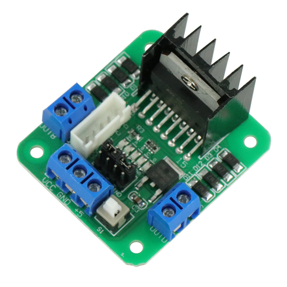
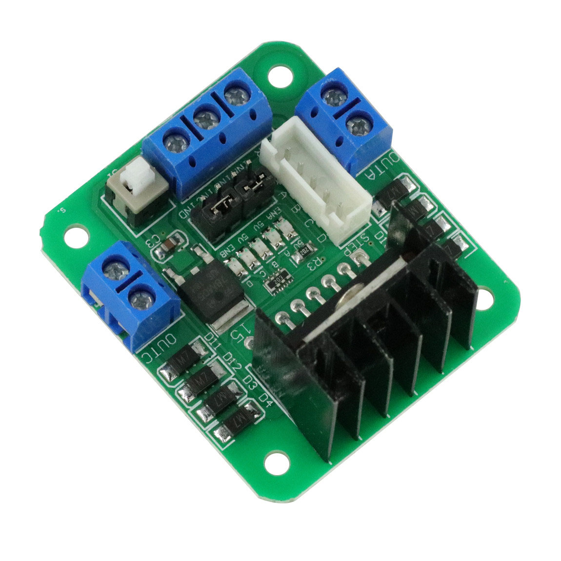
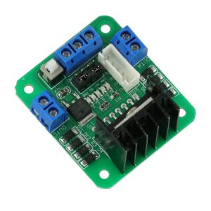
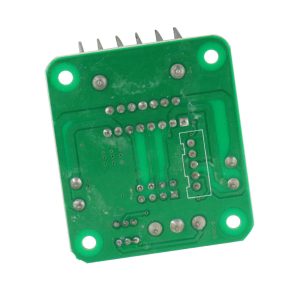
The Original L298N Dual H-Bridge Motor Driver Board is a high-performance, rugged, and versatile solution for controlling DC and stepper motors in your robotics, automation, and DIY projects. At its core is the legendary STMicroelectronics L298N integrated circuit, a dual full-bridge driver designed to handle high voltage and high current. This board acts as a powerful interface between your low-voltage microcontroller (like Arduino, Raspberry Pi, STM32, or ESP32) and your high-power motors, allowing you to precisely command motion.
Whether you are building a line-follower robot, a CNC machine, an automated window blind, or an industrial control system, this driver board provides the reliability and simplicity you need. It accepts standard TTL logic levels to control direction and uses Pulse Width Modulation (PWM) for smooth, efficient speed control. The onboard 5V regulator further simplifies your circuit design by providing power to the logic side in many common setups.
Key Features
-
Dual H-Bridge Topology: Based on the robust ST L298N chip, it features two independent H-bridge circuits. This allows you to control the direction and speed of two DC motors simultaneously or drive one bipolar stepper motor.
-
Wide Operating Voltage Range: Accepts a wide motor supply voltage (Vs) from +5V to +35V . This makes it compatible with a vast array of motors, including 5V, 6V, 9V, 12V, and 24V variants.
-
High Output Current: Capable of delivering a continuous 2A of current per channel, with peak currents up to 3A, providing ample power for motors requiring high starting torque .
-
PWM-Compatible Speed Control: Dedicated Enable pins (ENA and ENB) allow for precise speed regulation using PWM signals from your microcontroller. Simply connect these pins to a PWM-capable digital output for smooth acceleration and deceleration .
-
Onboard 5V Regulator (78M05): A convenient onboard voltage regulator can supply the 5V needed for the logic circuitry directly from the motor power supply (provided the motor voltage is between 7V and 12V). This eliminates the need for a separate logic power source in many standard projects .
-
Clear Status Indicators: Features onboard LEDs to indicate power presence and motor direction (A & B), making debugging and operation monitoring straightforward .
-
Built-in Protection Diodes: Includes flyback (snubber) diodes to protect the driver IC from voltage spikes generated by the inductive load of the motors during switching .
-
Robust Screw Terminals: Equipped with large, easy-to-use screw terminals for secure connections to your motors and power supply, ensuring reliability even under vibration.
-
Standard Logic Interface: Control inputs are TTL-compatible (5V logic), allowing for direct connection to most microcontrollers without the need for additional level-shifting circuitry .
Technical Specifications
| Parameter | Symbol | Min | Typical | Max | Unit |
|---|---|---|---|---|---|
| Motor Supply Voltage | Vs (VCC) | 5 | 12 | 35 | V |
| Logic Supply Voltage | Vss (5V) | 4.5 | 5 | 7 | V |
| Continuous Output Current (Per Channel) | I₀ | – | 2 | – | A |
| Peak Output Current (Per Channel) | I₀(peak) | – | – | 3 | A |
| Logic Input Current | Iᵢ | – | – | 36 | mA |
| Input Logic Low Voltage | Vᵢₗ | -0.3 | – | 1.5 | V |
| Input Logic High Voltage | Vᵢₕ | 2.3 | – | Vss | V |
| Maximum Power Dissipation | Pₜₒₜ | – | – | 25 | W |
| Operating Temperature | Tₒₚ | -25 | – | 130 | °C |
| Dimensions (Approx.) | – | – | 60 x 54 | – | mm |
| Weight (Approx.) | – | – | 30 – 48 | – | g |
Reviews
There are no reviews yet.