Product Overview
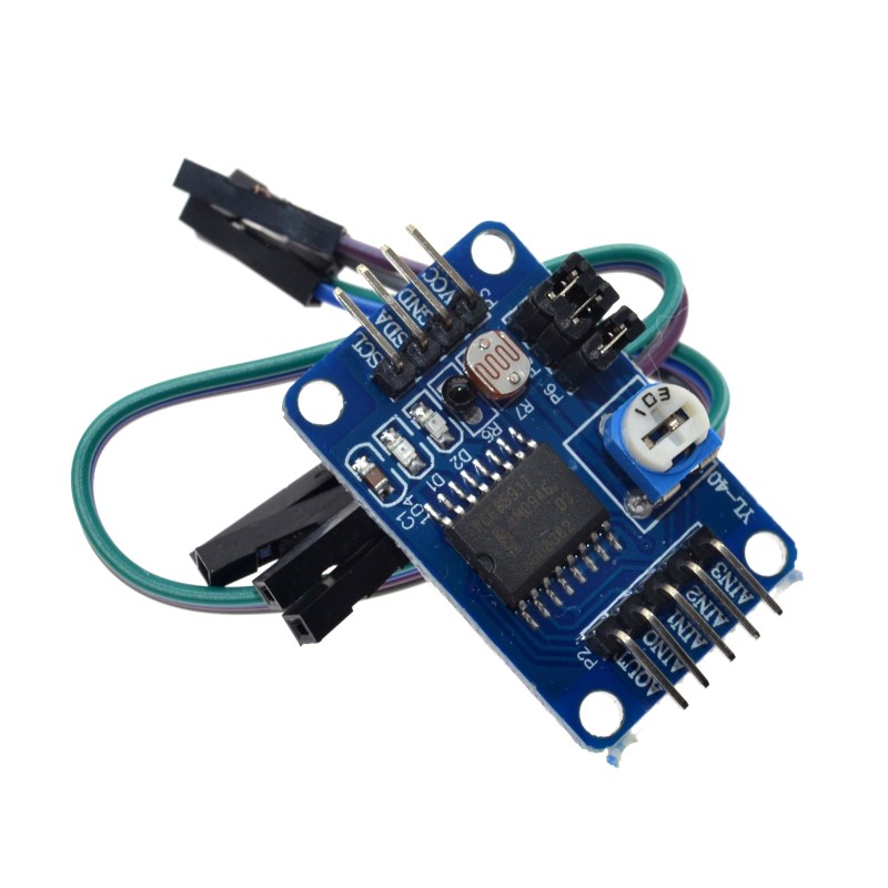
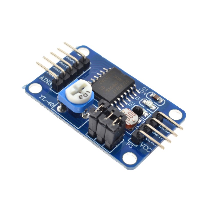
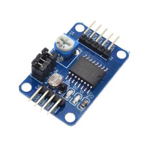
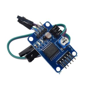
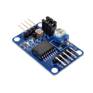
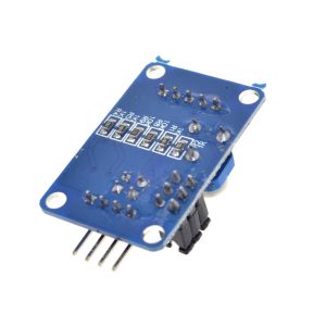
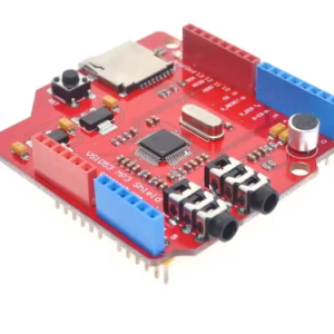
The PCF8591 AD/DA Converter Module is a versatile, low-power 8-bit data acquisition board based on the NXP (formerly Philips) PCF8591 chip. This small yet powerful module bridges the gap between analog sensors and digital microcontrollers like Arduino, ESP32, or Raspberry Pi, adding essential analog input and analog output capabilities to systems that lack them.
At its core, the PCF8591 integrates 4 analog inputs (for reading sensors) and 1 analog output (for controlling analog devices) into a single chip communicating via the simple 2-wire I2C bus. This design requires only two pins (SDA and SCL) to connect to your host system, making it an efficient solution for expanding your project’s sensing and control capabilities.
Key Features
-
4-Channel Analog Input (ADC): 4 configurable 0-5V analog input channels (AIN0–AIN3) for reading sensors like potentiometers, photoresistors, and temperature sensors.
-
1-Channel Analog Output (DAC): 1 analog output (AOUT) for controlling dimmable devices like LED brightness or the speed of small DC motors.
-
8-Bit Resolution: Both the ADC and DAC offer 8-bit resolution (values from 0 to 255), providing 256 steps of precision.
-
I2C Interface: Simple 2-wire communication (SDA, SCL) uses only two pins, saving valuable GPIO resources. Default I2C address: 0x48 (configurable).
-
Wide Voltage Support: Operates from 2.5V to 6V DC, with both 3.3V and 5V logic compatibility.
-
Multiple Input Modes: Four analog inputs are configurable as single-ended inputs or differential inputs for noise-sensitive applications.
-
Compact Form Factor: Miniature board size (approx. 23mm × 23mm) with 3mm mounting holes for easy installation in tight enclosures.
-
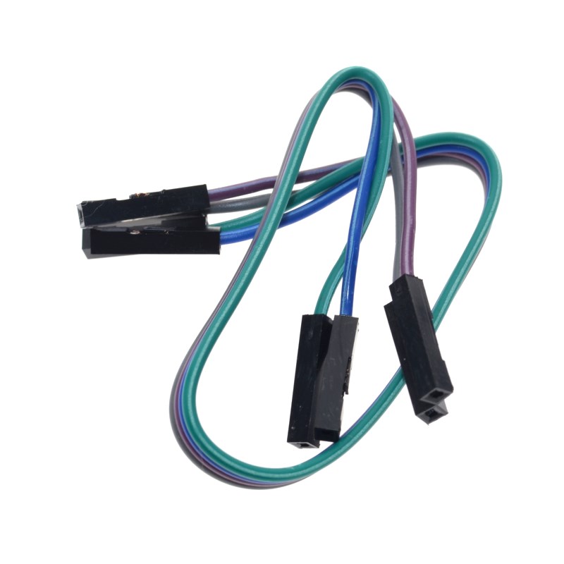
Complete Kit: Includes 4-Pin female-to-female jumper cable for immediate connection to your development board.
Technical Specifications
Pinout & Connection Guide
The PCF8591 module features a 4-pin I2C interface for easy connection. The pin labels are clearly marked on the PCB.
Pin Definitions
Wiring to Raspberry Pi
Note: On Raspberry Pi, you must enable the I2C interface in raspi-config before use.
Wiring to Arduino Uno
Usage Guide
Raspberry Pi Setup (Python)
The PCF8591 module is invaluable for Raspberry Pi projects because the Pi lacks built-in analog inputs.
Step 1: Enable I2C Interface
sudo raspi-config
sudo reboot
Step 2: Install Required Libraries
sudo apt-get install python3-smbus
pip3 install adafruit-circuitpython-pcf8591
Step 3: Basic Python Example — Reading Potentiometer & Controlling LED Brightness
This example reads the value from the potentiometer (connected to AIN0) and writes it to the analog output (AOUT), which controls the brightness of the D2 LED on the board.
import PCF8591 as ADC
import time
ADC.setup(0x48)
try:
while True:
potentiometer_value = ADC.read(0)
print(f"Potentiometer Value: {potentiometer_value}")
ADC.write(potentiometer_value)
time.sleep(0.2)
except KeyboardInterrupt:
print("Exiting")
Explanation: A jumper cap on the board connects the on-board potentiometer to AIN0 and the D2 LED to AOUT. Rotating the potentiometer generates a variable voltage (ADC input), which is read as a digital value (0–255). The microcontroller then immediately sends that value back to the DAC output (AOUT). This causes the LED’s brightness to vary proportionally as you turn the potentiometer.
Arduino Setup
The simplest way to use this module with Arduino is through the “PCF8591” library by Rob Tillaart (available via Library Manager).
Basic Arduino Sketch
#include <Wire.h>
#include "PCF8591.h"
PCF8591 adc;
void setup() {
Serial.begin(9600);
Wire.begin();
adc.begin(0x48);
adc.enableDAC();
}
void loop() {
uint8_t value = adc.analogRead(0);
Serial.println(value);
adc.analogWrite(value);
delay(100);
}
Understanding Input Modes
The PCF8591 chip supports four different analog input modes, configurable by writing to its control register:
Mode 0 (default) is suitable for most beginners, treating each of the 4 inputs as independent voltage inputs.
Hardware Setup Tips
-
Jumper Caps: The module includes jumper caps linking the onboard potentiometer to AIN0 and the D2 LED to AOUT. Ensure these are in place for the example code to work.
-
External Sensors: To connect external sensors (e.g., a photocell, temperature sensor, or joystick), remove the jumper cap on the desired AIN pin and wire your sensor to that pin.
-
Connect AOUT: To use the analog output, connect your analog device (e.g., LED, buzzer, small motor) to the AOUT pad. Note: The AOUT port on the Keyestudio version is an unsoldered hole that requires you to add your own header pins.
Q: Why do I need this PCF8591 module for my Raspberry Pi?
The Raspberry Pi does not have built-in analog-to-digital converters (ADC), meaning it cannot directly read analog sensors like potentiometers, photocells, or analog temperature sensors. The PCF8591 module provides 4 analog input channels to solve this problem. Additionally, it provides a DAC output to generate analog voltages (0–3.3V or 0–5V) for controlling analog devices.
Q: Can I connect more than one PCF8591 module to the same I2C bus?
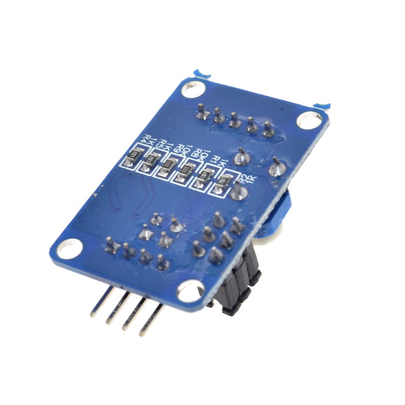
Yes. The PCF8591 chip has three hardware address pins (A0, A1, A2) that allow you to set up to 8 different addresses (0x48 to 0x4F). By soldering the address jumpers on the back of the module, you can connect multiple PCF8591 boards to the same I2C bus.
Q: How many analog inputs does this module provide?
The PCF8591 provides 4 analog inputs (AIN0–AIN3). However, these inputs are multiplexed internally, meaning you can only read one channel at a time. The chip automatically increments the channel selection after each read, or you can manually select the desired channel in your code
Q: What is the maximum voltage I can apply to the analog inputs?
The analog input voltage range is from 0V to VCC (the voltage you supply to the module). If you power the module at 5V, the inputs can safely read 0V–5V.
Q: How accurate is the 8-bit conversion?
With 8-bit resolution, the ADC divides the input voltage range (0–5V) into 256 steps (0 to 255). This means a resolution of approximately 19.5mV per step (5V ÷ 256). For many hobbyist applications (reading potentiometers, photocells, temperature sensors), this is sufficient. For higher precision applications, consider a 10-bit or 12-bit ADC module.
Q: Why is my analog output (AOUT) not working?
Common reasons:
-
The DAC output is disabled by default. In the Arduino code, you must call adc.enableDAC() or analogWrite() to enable it. In Python, the write() function handles this automatically.
-
The AOUT pin may need to be soldered. Some module versions have an unsoldered hole for the AOUT output; you must solder your own header pin or wire.
-
The chip’s DAC output current is very low (milliamps). For driving high-power loads, you must use a transistor or op-amp buffer.
Q: Can I use 3.3V logic (ESP32, Raspberry Pi) with this 5V module?
Yes. The PCF8591 chip operates from 2.5V to 6V. You can:
-
Power the module with 3.3V (connect VCC to 3.3V instead of 5V). For Raspberry Pi and ESP32, this is the recommended approach to avoid needing level shifters.
-
Or use 5V power with 3.3V logic: The I2C pins are generally 5V tolerant.
Q: How do I change the I2C address of the module?
The default address is 0x48 (all address pins connected to GND). To change the address, you must solder the address pads on the back of the PCB:
*Note: “1” means connect the pad to VCC (3.3V/5V) using a solder blob.*
Q: What are the four analog input modes for?
The different input modes allow you to configure the ADC for:
-
Single-ended mode (Default) : Each input reads voltage relative to ground (0–VCC). Best for connecting multiple independent sensors.
-
Differential modes: Measure the voltage differences between two inputs (e.g., AIN0+ vs AIN1-). This is useful for noise-sensitive applications or when you need to measure bipolar signals (e.g., from a thermocouple).
Q: What is included in the box?
The package includes:
1 x PCF8591 AD/DA Converter Module (Small Board)
1 x 4-pin Female-to-Female Jumper Cable