Product Overview
The PL2303TA Download Cable is a convenient and reliable USB to TTL serial converter cable designed to bridge the gap between your computer’s USB port and embedded systems requiring serial communication . Based on the Prolific PL2303TA chip, this cable provides a simple plug-and-play solution for programming, debugging, and communicating with microcontrollers, single-board computers, and other UART-enabled devices .
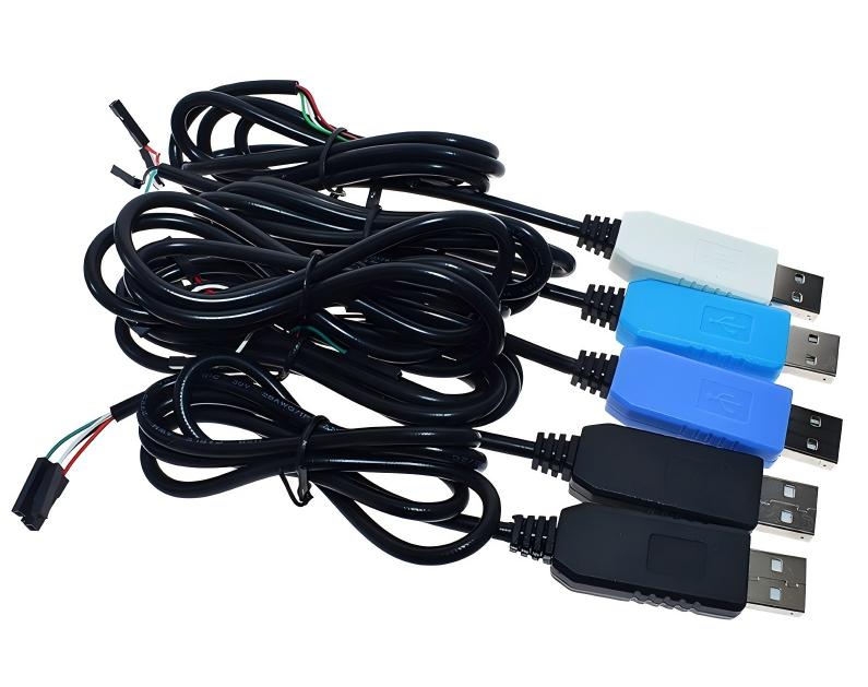
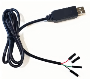
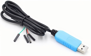
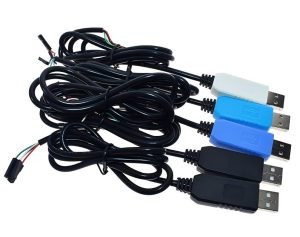
Unlike traditional USB-to-TTL adapters that come as bare boards, this cable integrates the conversion electronics directly into the USB connector housing, with four color-coded flying leads at the end. This design makes it exceptionally easy to connect to your target device using jumper wires or direct soldering .
The cable supports a wide baud rate range from 75 baud up to 6 Mbps (3 Mbps typical), making it suitable for both low-speed debugging and high-speed data transfer applications . With 5V power output (up to 500mA) and 3.3V logic level signaling on the TX/RX pins, it is compatible with a broad range of 3.3V logic level devices including Raspberry Pi, BeagleBone, ESP8266, ESP32, and many others .
The PL2303TA chip features a wide operating voltage range of 3.0V to 5.5V and industrial-grade temperature tolerance (-40°C to +85°C), making the cable suitable for both commercial and industrial applications . Whether you need to access a router’s console port, debug a microcontroller project, or upgrade firmware on legacy equipment, this download cable provides a straightforward and effective solution.
Key Features
-
Integrated PL2303TA Chipset: Based on the reliable Prolific PL2303TA USB-to-UART bridge controller, offering stable performance and broad compatibility
-
1 Meter Cable Length: Convenient length (approximately 36 inches) provides ample reach between your computer and target device
-
Pre-stripped Color-coded Wires: Four clearly identified flying leads (Red, Black, White, Green) for easy connection without needing a soldering iron or additional connectors
-
5V Power Output (500mA): Red wire provides 5V at up to 500mA from the USB port, capable of powering low-energy target devices directly
-
3.3V Logic Level Signaling: RX and TX pins operate at 3.3V levels, compatible with most modern microcontrollers and single-board computers
-
Dual Voltage Support: The PL2303TA chip operates from 3.0V to 5.5V, supporting both 3.3V and 5V logic systems
-
Cross-Platform Compatibility: Works with Windows (XP, 7, 8, 10, 11), macOS, and Linux systems
-
High-Speed Data Transfer: Supports baud rates from 75 baud up to 6 Mbps (3 Mbps typical), suitable for both debugging and high-speed applications
Technical Specifications
Pinout & Connection Guide
The cable features four color-coded wires at the output end. The pin assignments are as follows :
Important Wiring Notes:
-
The White wire (RXD) should be connected to the TX pin of your target device
-
The Green wire (TXD) should be connected to the RX pin of your target device
-
Always establish a common ground by connecting the Black wire (GND) to your target’s ground
Usage Guide
Raspberry Pi Debug Console Connection
The PL2303TA cable is commonly used to access the Raspberry Pi’s serial debug console without needing a separate display. Connect the wires as follows :
After connecting, configure your terminal software (e.g., PuTTY) to 115200 baud, 8 data bits, 1 stop bit, no parity (8-N-1) .
General Microcontroller Debugging / Programming
For most 3.3V logic microcontrollers, connect the cable as follows :
-
Connect GND (Black wire) to your target’s ground
-
Connect TX (Green wire) to your target’s RX pin
-
Connect RX (White wire) to your target’s TX pin
-
Optionally connect 5V (Red wire) if your target can be powered from USB (up to 500mA)
Router / Firmware Recovery
The cable is also popular for accessing the console ports of various WiFi routers and network equipment. The standard connection is the same: GND to GND, Green (TX) to Target RX, White (RX) to Target TX. Be careful not to connect the Red (5V) wire unless you are certain the device expects power from this port.
Important Usage Notes
Limitation for Arduino Reprogramming: This cable does not include a DTR (Data Terminal Ready) or RTS signal line. Consequently, it cannot automatically reset an Arduino during sketch upload, making it unsuitable for reprogramming Arduino boards that rely on a DTR signal to enter the bootloader . For that purpose, an FTDI cable or a USB-to-serial adapter with a DTR line is recommended.
Driver Installation Required:
-
Windows: Download the latest driver from the official Prolific website. For Windows 10/11, you may need to install older drivers or use compatibility settings
-
macOS: Official drivers are available for download
-
Linux: Support is built into the kernel (PL2303 driver). The device will typically appear as /dev/ttyUSB0
Driver Troubleshooting: If you encounter the error message “This is not a Prolific PL2303. Please contact your supplier” in Windows, install an older version of the Prolific driver and manually select it from the driver list in Device Manager .
Loopback Test: To verify the cable is functioning correctly, connect the Green (TXD) and White (RXD) wires together, open a serial terminal, and type characters. Any characters you type should be echoed back, confirming both the transmit and receive paths are working .
Power Considerations: The USB port can provide up to 500mA of current. Do not exceed this limit when powering external devices from the red wire. Ensure your target device’s total current draw is within this specification .
Logic Voltage Compatibility: The TX and RX pins operate at 3.3V logic levels. Avoid connecting these directly to 5V logic systems (such as classic 5V Arduinos) unless the target’s RX/TX pins are 5V tolerant, or use a level shifter to avoid potential damage to the target or the cable .
Q: What is the difference between the PL2303TA and the older PL2303HX?
The PL2303TA is a newer revision of the chip with industrial-grade temperature range (-40°C to +85°C) and improved driver support. It is a popular choice for the latest revisions of these programming cables .
Q: What is the maximum baud rate supported?
The PL2303TA chip supports baud rates from 75 baud up to 6 Mbps, with typical reliable operation up to 3 Mbps . The actual achievable speed depends on your computer’s processing power and the quality of your cables and connections.
Q: Is this cable compatible with macOS?
Yes, the PL2303TA is supported on macOS. Official drivers are available for download from the Prolific website, ensuring compatibility with recent versions of macOS .
Q: Is this cable compatible with Linux?
Yes, the PL2303 driver is built directly into the Linux kernel. When you plug in the cable, it should be automatically recognized and appear as /dev/ttyUSB0 .
Q: Is this cable suitable for programming STM32 "Blue Pill" boards?
Yes, many STM32 “Blue Pill” boards use a 3.3V UART bootloader. You can connect the cable to the board’s UART pins (PA9/PA10) and use the built-in bootloader to upload firmware, but note that you may need to manually manage the BOOT0 jumper to enter programming mode.
Q: Can I use this cable for Arduino reprogramming?
With limitations. Standard Arduino boards rely on a DTR (Data Terminal Ready) signal to automatically reset the board before uploading. This cable does not have a DTR wire, so it cannot initiate the auto-reset sequence. It will not work for uploading sketches to boards that depend on this signal .
Q: My computer doesn't recognize the device. What should I do?
Follow this checklist:
-
Ensure you have installed the correct drivers from the Prolific website
-
Try a different USB port on your computer
-
Check if the device appears in Device Manager with a yellow warning icon
-
On Windows, you may need to disable driver signature enforcement or install legacy drivers
-
On Windows 10/11, search online for solutions to “PL2303 Windows 10 driver” issues
Q: Why does Windows show "This is not a Prolific PL2303. Please contact your supplier"?
This message appears due to driver compatibility issues with counterfeit chips in some cheap cables or driver updates that lock out unauthorized clones. The solution is to install an older, compatible version of the Prolific driver and manually select it from the list in Device Manager
Q: Why are the TX/RX LEDs not blinking?
If your cable has status LEDs and they remain off, it likely indicates a driver issue. Verify that the drivers are properly installed and that the correct COM port is selected in your terminal software. Also ensure both ends of the communication link are correctly connected.
Q: I'm getting garbage characters in my terminal. What's wrong?
Check the following:
-
Ensure the baud rate matches your target device’s configuration (e.g., 115200 is common for Raspberry Pi and many devices)
-
Verify the data bits, stop bits, and parity settings (typically 8,1,N)
-
Check that the TX and RX connections are not swapped
-
Try a lower baud rate to test basic communication
Q: Can I power my device from the cable's 5V line?
Yes, with caution. The red wire provides 5V at up to 500mA, which is the standard maximum output of a USB port. This is sufficient for low-power devices like microcontrollers but will not power motors, high-power LEDs, or devices that draw more than 500mA. Check your device’s current requirements before relying on this power source .
Q: Can I use this for 5V logic devices (classic 5V Arduino Uno)?
The PL2303TA’s logic signals are 3.3V. While a 3.3V “HIGH” signal is often sufficient for a 5V target to recognize, the 5V target’s TX signal may exceed the 3.3V tolerance of the PL2303TA’s RX pin. For long-term reliability with 5V logic, a level shifter is recommended, or use a 5V-tolerant USB-to-serial adapter instead.
Q: What can I build with this PL2303TA download cable?
Popular applications include:
-
Raspberry Pi console access: Debugging without a monitor or network connection
-
Router firmware recovery: Accessing the serial console of routers to flash OpenWrt, DD-WRT, or recover bricked devices
-
Microcontroller programming: Uploading code to STM32, ESP8266, ESP32, and other 3.3V devices via UART bootloader
-
GPS module interfacing: Reading data from GPS receivers for computer-based navigation
-
Instrumentation & data logging: Capturing serial data from sensors and scientific instruments
-
Industrial equipment communication: Interfacing with legacy RS-232 devices through a TTL adapter
Q: What is the purpose of the 4-pin connector version?
The 4-pin version with color-coded wires is designed for maximum flexibility. It allows you to easily connect to a wide variety of target devices using standard jumper wires, unlike cables that come with a pre-attached female socket that may not fit your specific target’s pinout .
Q: Is there a way to add DTR to this cable for Arduino support?
Not directly, as the PL2303TA chip does not expose the DTR signal in this cable’s configuration. For Arduino programming, it is better to purchase a purpose-built USB-to-serial adapter that specifically includes a DTR (or RTS) pin, such as an FTDI basic or a CP2102 module with a dedicated DTR line.