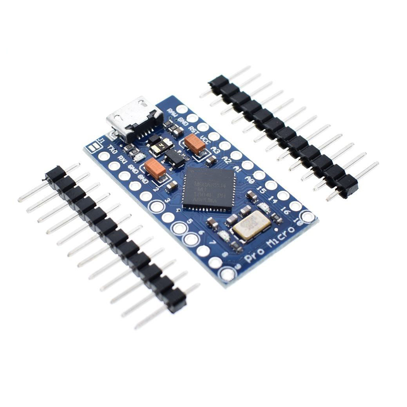
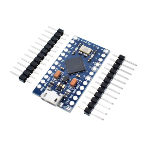
Number of pins: 18+2
The Arduino Pro Micro has 18 easily accessible pins, that’s theoretically enough for a board with up to 81 keys (9*9).
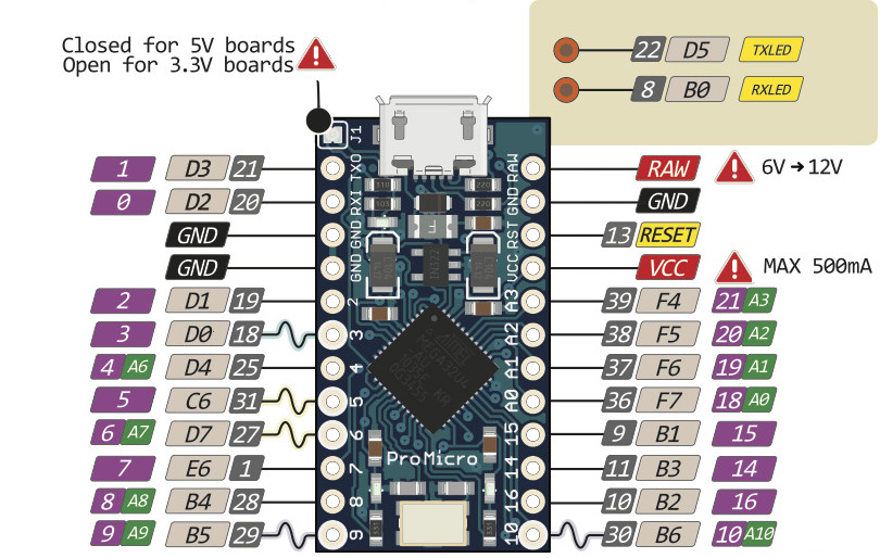
However, there are 2 more pins, used by the onboard LEDs, which can be quite easily turned into usable pins. Just follow my Pro Micro upgrade guide and solder your wire to the pad of the removed resistors of the RX/TX LEDs. This way you can wire up a board with up to 100 keys (using the 18+2 pins in a matrix of 10 rows and 10 columns).
The additional pins are B0 and D5 as described in the ATmega16U4/32U4 data sheet.
The Atmega32u4 has even more GPIO pins (26), which could be available by soldering directly to the microcontroller, but that’s not really for beginners.
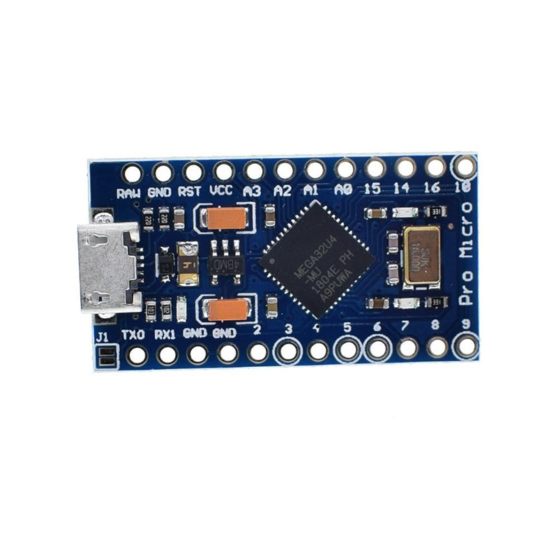
Pinout & pin names
If you use the Pro Micro outside the Arduino IDE (e.g. with QMK), you’ll have to translate the pin names marked on its PCB to the AVR ones. E.g. pin 3 on the Pro Micro is called D0 on the Atmega32u4.
Arduino makes it confusing by not mapping its pin numbers to AVR ports, but this is for a reason. Some pins on the AVR can also be used for special purposes such as serial, timer input, PWM output, etc. and they are therefore sometimes labelled by those functions on the Pro Micro.
Here is the Pinout:
Arduino pins to AVR ports. This is a table to translate the Arduino pin names marked on the silk screen into ARV ports, ordered more or less alphabetically:
| Arduino |
AVR |
| TX0 |
D3 |
| RX1 |
D2 |
| 2 |
D1 |
| 3 |
D0 |
| 4 |
D4 |
| 5 |
C6 |
| 6 |
D7 |
| 7 |
E6 |
| 8 |
B4 |
| 9 |
B5 |
| 10 |
B6 |
| 14 |
B3 |
| 15 |
B1 |
| 16 |
B2 |
| A0 |
F7 |
| A1 |
F6 |
| A2 |
F5 |
| A3 |
F4 |
| LED pin (left of crystal) |
B0 |
| LED pin (right of crystal) |
D5 |
AVR ports to Arduino pin names.
The same data as above, this time in order of the AVR codes to make translating from AVR to Arduino easier:
| AVR |
Arduino |
| B0 |
LED pin (left of crystal) |
| B1 |
15 |
| B2 |
16 |
| B3 |
14 |
| B4 |
8 |
| B5 |
9 |
| B6 |
10 |
| C6 |
5 |
| D0 |
3 |
| D1 |
2 |
| D2 |
RX1 |
| D3 |
TX0 |
| D4 |
4 |
| D5 |
LED pin (right of crystal) |
| D7 |
6 |
| E6 |
7 |
| F4 |
A3 |
| F5 |
A2 |
| F6 |
A1 |
| F7 |
A0 |
Voltage
The Pro Micro has a built-in voltage regulator (it was designed to run on batteries).
There are two variants of the Pro Micro: One which feeds the AVR 3.3V, and one which is made to feed it 5V – the 5V version being the most common.
If you do feed it with +5.0V from USB, however, there is a penalty – the voltage regulator will deliver only +4.9V.
The AVR should run well on 4.9V, but you could also bypass the voltage regulator by bridging J1 with solder.
- RAW = +5V from the USB port (or power IN if you use battery).
- VCC = +4.9V (or 3.3V) from the voltage regulator, or +5V if bypassed.
On 3.3V, the AVR is limited to 8 MHz and the firmware needs to be made for it but since most firmwares are made for the Teensy 2.0 which runs always on 5V, if you have the 3.3V of the Pro Micro you should bridge J1 to run that firmware.