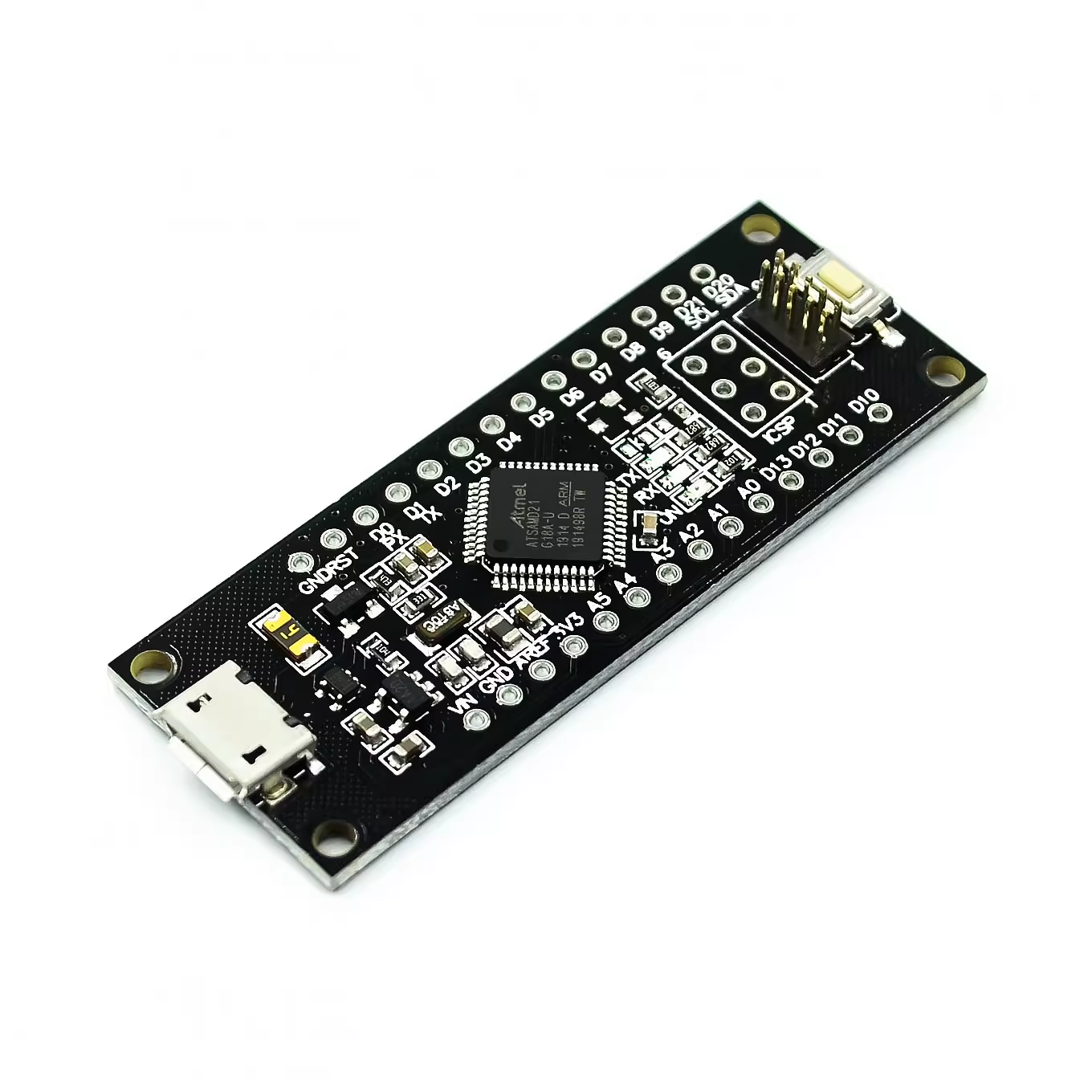
SAMD21 Mini 32-bit ARM Cortex-M0+ Microcontroller – SMD Version (Bare Chip)
The Microchip SAMD21 Mini SMD Version refers to the standalone ATSAMD21G18A bare integrated circuit (IC) provided in a surface-mount device (SMD) package (typically TQFP-48). This component is the core processing unit behind popular development boards like the Arduino Zero, MKR Zero, and Feather M0 series.
This product is not a ready-to-use development board with pins or USB ports; it is the raw microcontroller chip intended for professional use in custom PCB design and high-volume manufacturing. It offers engineers a powerful, cost-effective 32-bit ARM Cortex M0+ solution running at 48MHz with 256KB Flash and 32KB SRAM. It requires specialized manufacturing processes (SMD soldering) to integrate into a final product design.
Key Features
- Bare SMD Chip (ATSAMD21G18A): Intended for direct integration onto custom-designed printed circuit boards (PCBs) using pick-and-place manufacturing processes.
- Powerful 32-bit Architecture: Utilizes the energy-efficient ARM Cortex M0+ core, offering significantly higher performance than traditional 8-bit MCUs (like the ATmega328P).
- Rich Memory Footprint: Features 256KB of Flash memory and 32KB of SRAM, ample space for complex applications, communication stacks, and data buffering.
- Integrated USB Controller: Includes a full-speed USB 2.0 interface for native USB host/device capabilities without external components (requires appropriate PCB design).
- Advanced Peripherals: Offers multiple serial communication interfaces (I2C, SPI, UART), a 12-bit ADC, a 10-bit DAC, and advanced timers (TCC).
- Low Power Consumption: Designed with intelligent peripheral management (PAC) and multiple sleep modes for efficient battery-powered IoT devices.
- Flexible Voltage Operation: Operates within a supply voltage range of 1.62V to 3.6V.
Technical Parameters (Specifications)
| Parameter |
Value/Description |
| Microcontroller |
ATSAMD21G18A-AU / -MUT (Varies by package) |
| Core Architecture |
32-bit ARM Cortex M0+ |
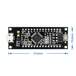
| Package Type |
TQFP-48 (Thin Quad Flat Pack 48-pin) |
| Clock Speed |
Up to 48 MHz |
| Operating Voltage Range |
1.62V – 3.6V DC (Typically used at 3.3V) |
| Flash Memory |
256 KB |
| SRAM |
32 KB |
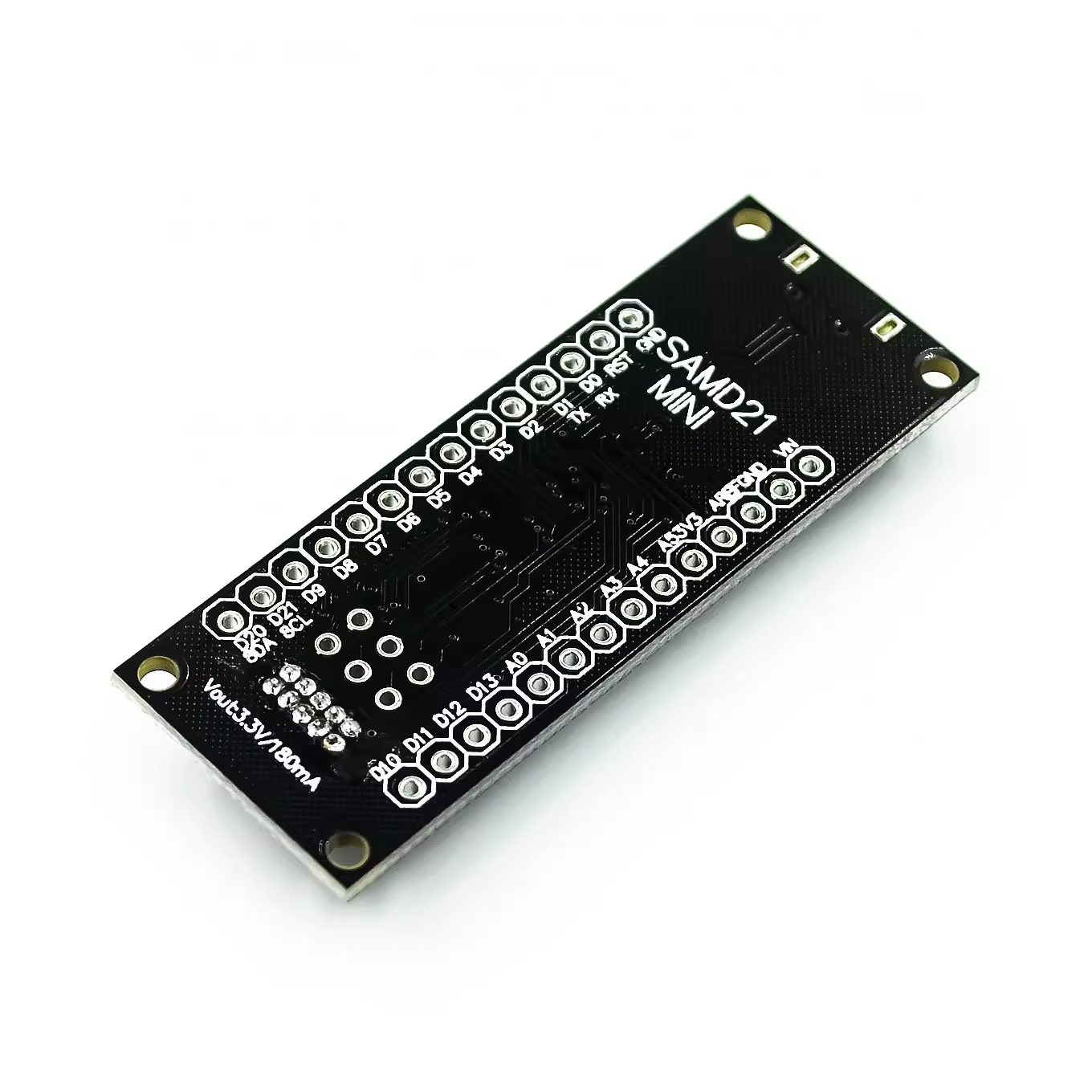
| GPIO Pins |
Up to 38 pins (depending on TQFP-48 package implementation) |
| Communication |
3x SERCOM (configurable as UART, I2C, SPI), USB 2.0, I2S |
| Analog Peripherals |
12-bit ADC (up to 14 channels), 10-bit DAC, Analog Comparators |
| Debugging Interface |
SWD (Serial Wire Debug) |
Usage Instructions
This bare chip is not for hobbyist prototyping on a breadboard. It is exclusively for use in custom PCB manufacturing processes.
Design and Manufacturing:
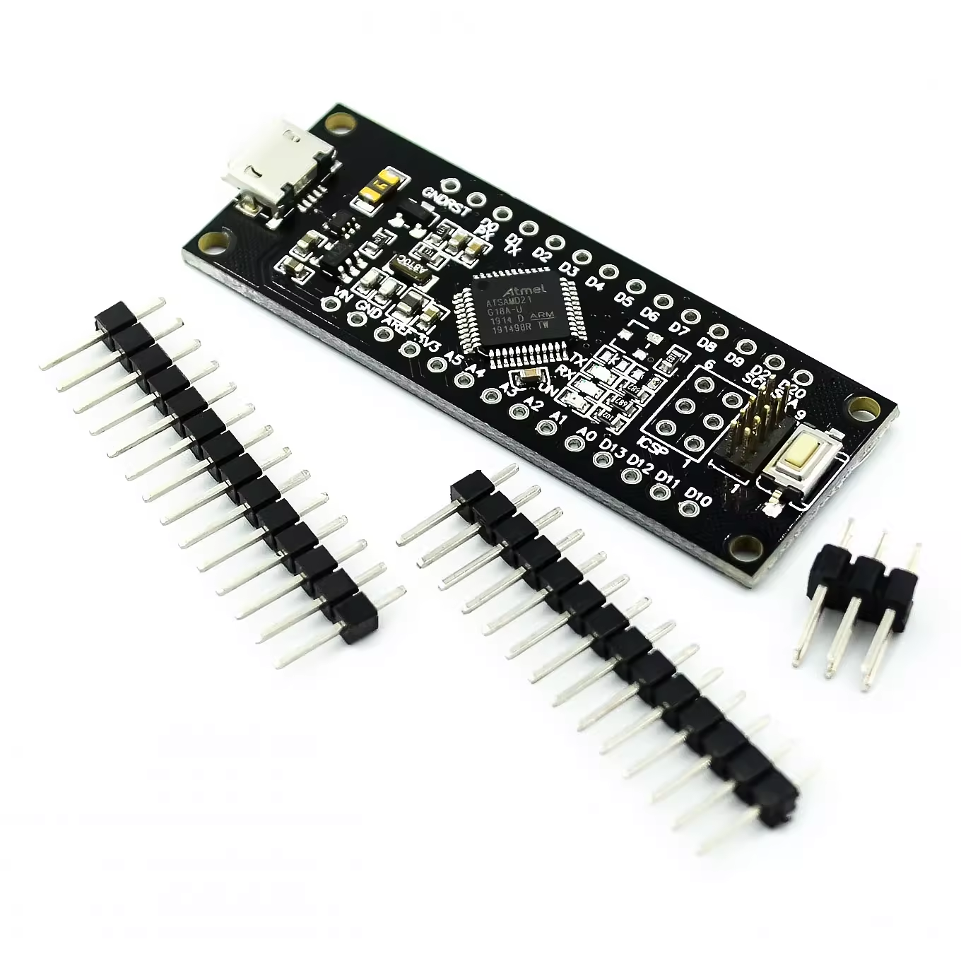
- Custom PCB Design: An electrical engineer must design a custom printed circuit board (PCB) using CAD software (KiCad, Altium, Eagle). This design must include all necessary supporting circuitry for the SAMD21, including power regulation (3.3V), a 32.768kHz crystal (for the RTC), the 48-pin TQFP footprint, and a connector for programming/debugging (usually an SWD header or a micro-USB port if native USB is implemented).
- Manufacturing: The design files are sent to a PCB fabrication house. The bare SMD chips are soldered onto the boards using automated pick-and-place machines and reflow ovens.
- Programming (Flashing Bootloader): The blank chip usually needs an initial bootloader (like the Arduino UF2 bootloader or a custom DFU) flashed onto it using an external hardware debugger/programmer via the SWD interface (e.g., a J-Link or EDBG programmer).
- Application Code: Once the bootloader is installed, the chip can typically be programmed via the USB port or the SWD interface using the Arduino IDE or Microchip Studio.
Q: I am a hobbyist and bought this for my Arduino Uno project. How do I use it?
This bare SMD chip is unsuitable for hobbyist use unless you are designing and assembling your own custom PCBs. You likely need a pre-assembled development board like the SAMD21 M0 development board that already has all support components and pins broken out.
Q: Does this chip come pre-loaded with the Arduino bootloader?
Usually not. Bare chips from the manufacturer typically ship blank. You will need an external SWD programmer (like a J-Link) to flash the Arduino bootloader or a DFU bootloader onto the chip’s Flash memory the first time.
Q: What voltage does this chip use?
The core logic runs at 3.3V. The voltage range is flexible (1.62V to 3.6V), but 3.3V is the standard operating voltage for I/O and power supply in most designs.
Q: I am a business buyer/engineer. Can I get these in bulk (reels)?
Yes, these components are available in standard tape-and-reel packaging for high-volume automated manufacturing. Please contact our sales team for large quantity pricing and MOQ details.
Q: How does this compare to the ATmega328P chip (used in Arduino Uno)?
The SAMD21 is a generation ahead: 32-bit vs. 8-bit, 48MHz vs. 16MHz, much more RAM/Flash, and native USB support. It is significantly more capable for complex applications.