STM8S003F3P6 Microcontroller Development Board – Embedded Programming Core Learning Module (Minimal System) Micro usb interface

SKU: FA2174-2
Microcontroller

STM8S003F3P6 (8-bit, STM8 core, Value Line)

Clock Speed

Up to 16 MHz

Flash Memory

8 Kbytes

RAM

1 Kbyte

EEPROM

128 bytes (true data EEPROM, 100k cycles endurance)

Operating Voltage (MCU)

2.95V – 5.5V DC

Input Voltage (Board)

4.5V – 15V DC (via power pads or Micro USB)

Digital I/O Pins

Up to 16 (all broken out to headers)

ADC Channels

5 × 10-bit

Communication Interfaces

UART (with LIN, IrDA, SmartCard), SPI (up to 8 Mbit/s), I²C (up to 400 Kbit/s)

Timers

Advanced 16-bit timer (4 CAPCOM channels, 3 complementary outputs), 16-bit general purpose timer, 8-bit basic timer, auto wakeup timer, watchdog timer

Programming Interface

SWIM (Single Wire Interface Module

Board Dimensions

Approx. 36.5mm × 21.6mm

Description

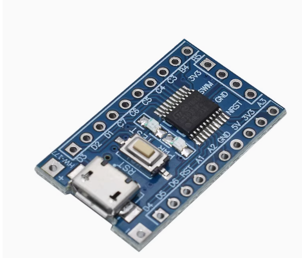
The STM8S003F3P6 Minimum System Development Board is an ultra-low-cost, compact, and powerful entry point into the world of STM8S microcontroller development. Built around the robust STM8S003F3P6 8-bit MCU from STMicroelectronics, this core board is specifically designed as a value-line solution, offering an exceptional balance of performance, robustness, and reduced system cost for cost-sensitive applications .

As part of ST’s “Value Line,” this microcontroller is optimized for applications where budget is a primary constraint but reliability cannot be compromised. It features a 16 MHz advanced STM8 core with Harvard architecture and a 3-stage pipeline, providing efficient processing for a wide range of embedded tasks . With 8 Kbytes of Flash program memory1 Kbyte of RAM, and 128 bytes of true data EEPROM, this MCU delivers a solid feature set for learning, prototyping, and low-to-medium volume production .

This development board breaks out all microcontroller pins to standard 2.54mm headers with clear silkscreen labeling, making it easy to integrate into breadboards or custom PCBs. The Micro USB interface serves as a convenient power input, compatible with common smartphone charging cables and power banks.

The board includes a SWIM (Single Wire Interface Module) connector for programming and debugging, a reset button for easy system restart, and a user LED for basic output testing. An onboard AMS1117-3.3 voltage regulator allows the board to accept input voltages from 4.5V to 15V via the power pads or the Micro USB port .

Whether you are a student learning embedded systems fundamentals, a hobbyist building cost-effective DIY projects, or a professional developing high-volume consumer electronics, this STM8S003F3P6 minimum system board delivers exceptional value in a tiny footprint.

Key Features

  • STM8S003F3P6 Value Line Microcontroller – 16MHz advanced STM8 core with Harvard architecture and 3-stage pipeline; optimized for cost-sensitive applications 

  • Memory Resources – 8 Kbytes Flash, 1 Kbyte RAM, 128 bytes true data EEPROM (100k write/erase cycles endurance) 

  • Micro USB Power Interface – Convenient power input using common smartphone cables; compatible with Micro USB chargers and power banks 

  • All Pins Broken Out – All 16 I/O pins accessible via 2.54mm headers for easy breadboard and PCB integration 

  • SWIM Programming Interface – Single-wire debug and programming port for use with ST-Link programmers 

  • Onboard Reset Button – Physical reset button for easy system restart during development 

  • User LED – Built-in LED connected to PD3 for basic output testing and debugging 

  • Power LED Indicator – Visual confirmation of board power status 

  • Wide Power Input Range – 4.5V to 15V input via power pads; onboard AMS1117-3.3 regulator converts to 3.3V for MCU 

  • Rich Peripherals – 10-bit ADC (5 channels), UART, SPI, I²C, multiple timers (advanced 16-bit, general purpose 16-bit, 8-bit basic, auto wakeup) 

  • Reserved Crystal Oscillator Footprint – Allows for external crystal oscillator installation for applications requiring higher timing accuracy 

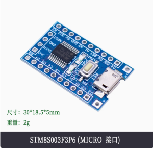
  • Compact Form Factor – Approximately 36.5mm × 21.6mm board size for space-constrained projects 

Technical Specifications 

Specification Value
Microcontroller STM8S003F3P6 (8-bit, STM8 core, Value Line)
Clock Speed Up to 16 MHz 
Flash Memory 8 Kbytes 
RAM 1 Kbyte 
EEPROM 128 bytes (true data EEPROM, 100k cycles endurance) 
Operating Voltage (MCU) 2.95V – 5.5V DC 
Input Voltage (Board) 4.5V – 15V DC (via power pads or Micro USB) 
Digital I/O Pins Up to 16 (all broken out to headers) 
ADC Channels 5 × 10-bit 
Communication Interfaces UART (with LIN, IrDA, SmartCard), SPI (up to 8 Mbit/s), I²C (up to 400 Kbit/s) 
Timers Advanced 16-bit timer (4 CAPCOM channels, 3 complementary outputs), 16-bit general purpose timer, 8-bit basic timer, auto wakeup timer, watchdog timers 
Programming Interface SWIM (Single Wire Interface Module) 
Board Dimensions Approx. 36.5mm × 21.6mm 
Operating Temperature -40°C to +85°C (Industrial grade) 

Typical Usage

  • Embedded Systems Learning – Ideal for students and beginners learning 8-bit microcontroller programming, C coding for embedded systems, and register-level programming

  • Cost-Sensitive Consumer Electronics – Low-cost remote controls, small appliances, electronic toys, and basic user interface controllers

  • Industrial Control – Simple motor control applications using the advanced 16-bit timer with complementary outputs

  • Home Automation – Smart home devices, sensor interfaces, and actuator control with I²C and SPI communication

  • IoT Edge Devices – Low-power sensor nodes with periodic wake-up using the auto-wake-up timer (low-power wait, active-halt, halt modes) 

  • LED Lighting Control – PWM generation for RGB LED control and dimming applications

  • Prototype Development – Rapid proof-of-concept for products before custom PCB design

  • Data Logging – Store small amounts of calibration data or user settings in the integrated 128-byte EEPROM

  • Communication Bridges – Simple interface conversion between UART, SPI, and I²C protocols

  • Educational Projects – Learn about microcontroller fundamentals, timer operations, ADC sampling, and serial communication

Q: What is the difference between STM8S003F3P6 and STM8S103F3P6?

These are two popular STM8S series microcontrollers with key differences. The STM8S003F3P6 is the Value Line version with 128 bytes of EEPROM and is optimized for cost-sensitive, high-volume production. The STM8S103F3P6 has 640 bytes of EEPROM and is intended for development and prototyping . The 003 version offers lower cost but with reduced EEPROM size and Flash write endurance (100 cycles vs 10,000 cycles on the 103 at 55°C) . For learning and development, the 103 is often preferred; for high-volume production where cost is critical, the 003 is the better choice.

Q: How do I program this board?

You need an ST-Link programmer (ST-Link V2 or compatible). Connect the programmer to the board’s SWIM interface (typically 4 pins: VCC, GND, SWIM, RESET). Use STMicroelectronics’ STVP (ST Visual Programmer) or open-source tools like SDCC with stm8flash. The SWIM interface uses a single wire for programming and debugging, making it simple to use .

Q: Does this board have a bootloader? Can I program via USB?

No. The Micro USB port on this board is for power only, not for programming. Unlike many ARM-based development boards (e.g., Arduino), this STM8S board does not have a USB bootloader. You must use an external ST-Link programmer connected to the SWIM header .

Q: What is the input voltage range and how should I power the board?

The board accepts 4.5V to 15V DC input via the power pads, or 5V via the Micro USB port. An onboard AMS1117-3.3 regulator provides stable 3.3V power to the microcontroller . Do not exceed 15V, as this may damage the voltage regulator. The “5V” pin on the header is directly connected to the input voltage (not a regulated 5V output) .

Q: What is the EEPROM endurance and how should I use it?

The 128-byte true data EEPROM has an endurance of 100k write/erase cycles and data retention of 20 years at 55°C . This is suitable for storing calibration data, configuration settings, or user preferences that are updated occasionally. For frequently updated data (e.g., logging every second), consider using RAM instead or implement wear-leveling algorithms.

Q: What development tools are available for this microcontroller?

Several options exist:

  • STVD (ST Visual Develop) – Free IDE from STMicroelectronics

  • COSMIC C compiler – Free for STM8 up to 32KB (limited edition)

  • SDCC (Small Device C Compiler) – Complete open-source option

  • IAR Embedded Workbench for STM8 – Commercial option with free size-limited version

  • STVP – Programming utility for flashing hex files 

Q: What communication interfaces are available on this board?

The STM8S003F3P6 supports:

  • UART – Full-duplex serial communication with clock output for synchronous operation, plus LIN, SmartCard, and IrDA modes 

  • SPI – Synchronous serial up to 8 Mbit/s 

  • I²C – Two-wire interface up to 400 Kbit/s 
    All pins are broken out to the headers for easy connection to sensors, displays, and other peripherals.

Q: Can I use this board with Arduino IDE?

Not directly. The Arduino IDE does not natively support STM8 microcontrollers. However, community projects like Sduino (STM8duino) provide Arduino-style wrappers and libraries for the STM8 family, allowing you to use a simplified coding approach with SDCC compiler. This is an option for developers familiar with Arduino but requires additional setup.

Q: Is this board suitable for commercial or industrial products?

Yes. The STM8S003F3P6 is rated for industrial temperature range (-40°C to +85°C) . The value line is specifically designed for cost-sensitive, high-volume applications such as consumer electronics, small appliances, and industrial controls. Many businesses use this board for prototyping and then transfer the design to a custom PCB for mass production.

Q: What are the key timer features available on this MCU?

The STM8S003F3P6 includes multiple timers for various applications :

  • Advanced 16-bit timer – 4 capture/compare channels, 3 complementary outputs, dead-time insertion (ideal for motor control)

  • 16-bit general purpose timer – 3 CAPCOM channels for input capture, output compare, or PWM

  • 8-bit basic timer – With 8-bit prescaler

  • Auto wakeup timer – For low-power periodic wake-ups from halt/active-halt modes

  • Window watchdog and independent watchdog – For system reliability