Product Overview
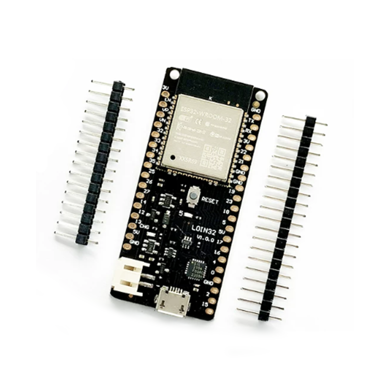
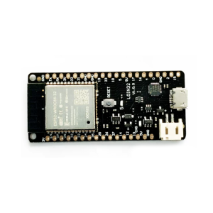
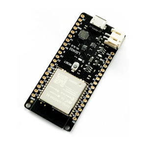
The Wemos D1 V1.0.0 ESP32 Development Board (also known as the LOLIN32) is a powerful, feature-packed IoT development board that combines the immense capabilities of the ESP32 dual-core processor with the convenience of a compact, breadboard-friendly form factor. This board is an ideal upgrade path from ESP8266-based boards, offering built-in WiFi and Bluetooth (BLE) connectivity, significantly more processing power, and a lithium battery charging circuit for portable applications.
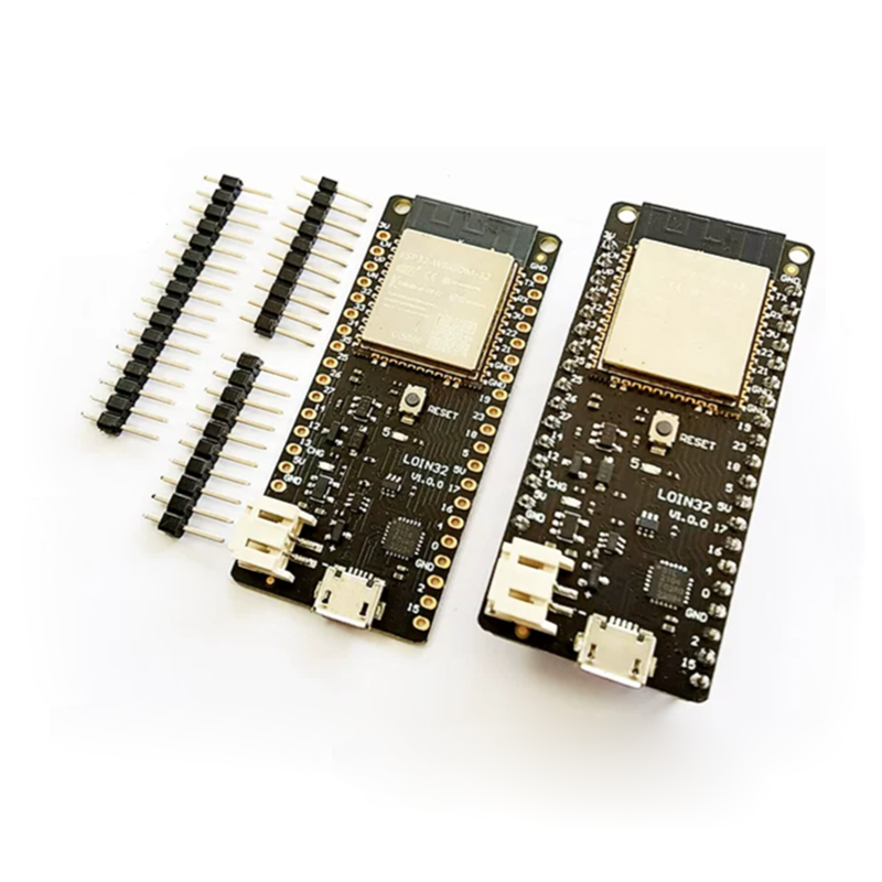
Unlike standard NodeMCU ESP32 boards that lack native battery support, the Wemos D1 ESP32 features an onboard LiPo battery connector and charging circuit. This allows your projects to run on a single 3.7V lithium battery, which can be recharged directly via the USB port, with a maximum charging current of 500mA. The board’s ultra-low power consumption (deep sleep current as low as 0.015mA) makes it perfect for battery-powered IoT sensors, wearable devices, and remote monitoring systems.
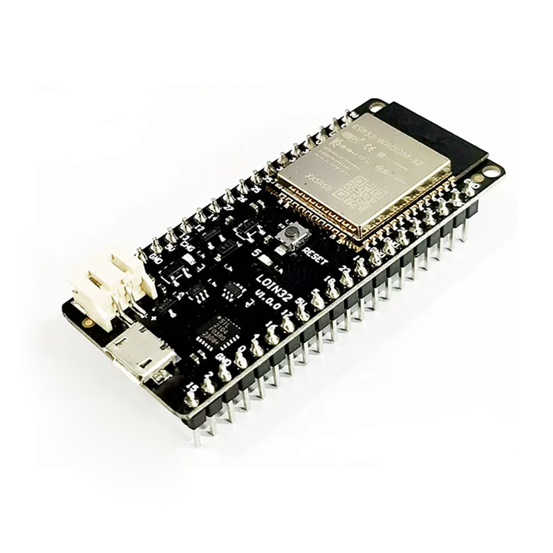
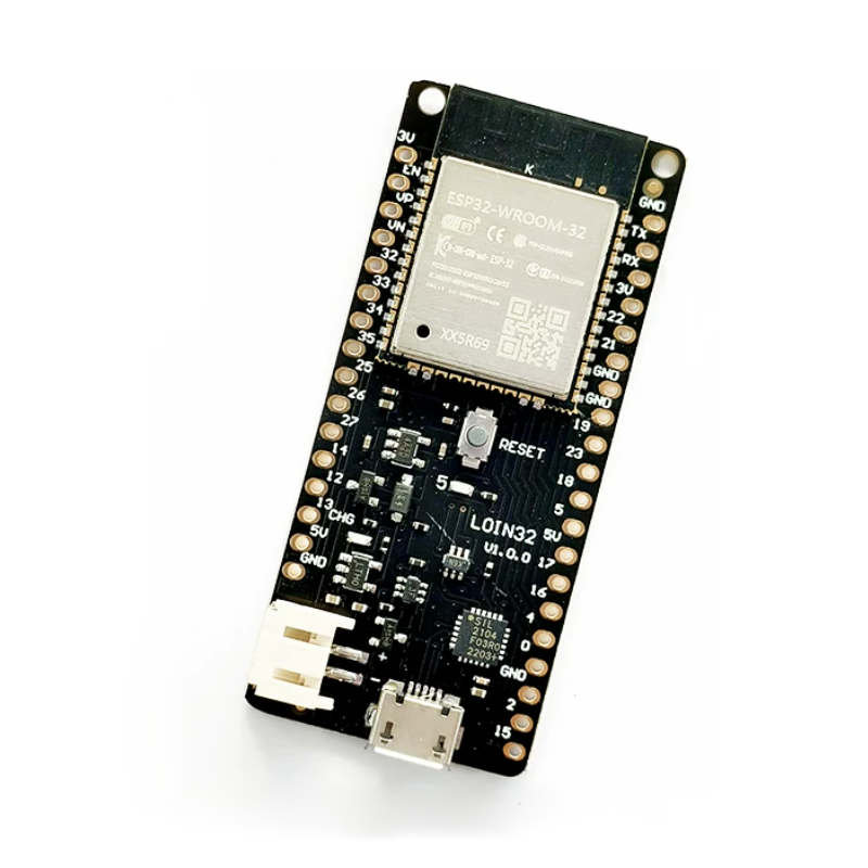
The board is equipped with the ESP-WROOM-32 module, which houses a Tensilica Xtensa 32-bit LX6 dual-core processor running at up to 240 MHz, with 4MB of flash memory and 520KB of SRAM. It uses the reliable CP2104 USB-to-serial chip, ensuring stable communication and easy programming via the Arduino IDE. All 26 digital I/O pins and 12 analog inputs are clearly labeled and broken out, making it simple to connect sensors, actuators, and displays.
Key Features
-
ESP-WROOM-32 Module: Powered by the Espressif ESP32 dual-core processor with integrated WiFi 802.11 b/g/n and Bluetooth 4.2 (BLE) for versatile wireless applications.
-
LiPo Battery Support: Onboard PH2.0 battery connector and charging circuit allow the board to run on a single-cell lithium battery and be recharged via USB (max charging current 500mA).
-
CP2104 USB-to-Serial Chip: High-quality USB interface chip ensures reliable communication, stable driver support, and easy programming across Windows, macOS, and Linux.
-
4MB Flash Memory: Ample storage for complex IoT applications, OTA (Over-The-Air) firmware updates, and data logging.
-
26 Digital I/O Pins: Includes support for UART, I2C, SPI, DAC, capacitive touch sensors, and PWM outputs—breaks out most of the ESP32’s peripheral functions.
-
12 Analog Inputs (12-bit ADC): Integrated high-resolution analog-to-digital converter for reading sensors like potentiometers, temperature sensors, and joysticks.
-
Compact & Breadboard-Compatible: Measures approximately 58mm x 25.4mm (similar to D1 mini but slightly longer), fitting neatly on a breadboard with ample space for connections.
-
User LED & Reset Button: Onboard programmable LED (GPIO2) for status indication and a central reset button for easy debugging.
Technical Specifications
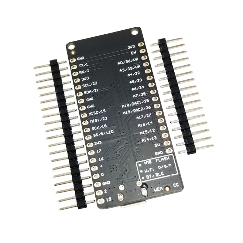
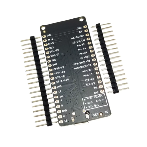
Pinout & Interface Guide
The Wemos D1 V1.0.0 uses a pinout similar to the D1 mini form factor, which is slightly different from standard Arduino shields. However, it brings out most of the ESP32’s essential pins.
Important Notes:
Usage Guide
Arduino IDE Setup
To program the Wemos D1 ESP32 board, you need to install the ESP32 board package in the Arduino IDE.
-
Install Arduino IDE: Download and install the latest version from the official website.
-
Add ESP32 Board Manager URL:
-
Open Arduino IDE → File → Preferences.
-
In “Additional Boards Manager URLs”, add the following URL:
https://raw.githubusercontent.com/espressif/arduino-esp32/gh-pages/package_esp32_index.json
(If you have multiple URLs, separate them with commas).
-
Install ESP32 Board Package:
-
Select Your Board:
-
Select the COM Port:
First-Time Setup & Driver Installation
-
CP2104 Driver: If your computer does not automatically recognize the board, you may need to install the CP2104 USB-to-serial driver. Download the driver from the Silicon Labs website and install it.
-
Power-On: You can power the board via the Micro-USB port or by connecting a 3.7V Li-ion battery to the PH2.0 connector. The board will automatically use USB power when both are connected.
Example Code (Blink)
To test your setup, upload the classic blink sketch. The onboard LED is connected to GPIO2.
#define LED_PIN 2
void setup() {
pinMode(LED_PIN, OUTPUT);
Serial.begin(115200);
}
void loop() {
digitalWrite(LED_PIN, HIGH);
Serial.println("LED ON");
delay(1000);
digitalWrite(LED_PIN, LOW);
Serial.println("LED OFF");
delay(1000);
}
Uploading Code
-
Select the correct Board and Port from the Tools menu.
-
Click the Upload button (right arrow).
-
Some boards may require you to hold the BOOT button while uploading, but the Wemos D1 ESP32 typically handles this automatically. If you encounter upload errors, press and hold the BOOT button, click reset once, release BOOT, then try uploading again.
Battery Operation
The board features a PH2.0 2-pin connector for a single-cell 3.7V Li-ion or LiPo battery. Simply plug in the battery, and the board will run from battery power. When you connect USB, it will charge the battery (if a battery is present) at a maximum current of 500mA. This makes it perfect for portable and untethered IoT projects.
Q: What is the difference between this board and a standard NodeMCU ESP32?
The main difference is the integrated battery charging circuit and PH2.0 battery connector on the Wemos D1 ESP32. Standard NodeMCU boards cannot be directly powered from a single-cell lithium battery or charge one via USB. The Wemos board also uses the CP2104 USB chip, while some NodeMCUs use CH340.
Q: Can I use Arduino shields with this board?
The Wemos D1 ESP32 uses the D1 mini form factor, which is physically different from standard Arduino shields. While it is breadboard-friendly, it is not mechanically compatible with standard Arduino Uno shields. However, you can use D1 mini-compatible shields available from various vendors.
Q: How long will the battery last when running on deep sleep?
The ESP32 has excellent low-power capabilities. In deep sleep mode, the board can consume as little as 0.015mA (15µA). With a standard 2000mAh Li-ion battery, this could theoretically last for years. Actual battery life depends on how often the board wakes up, transmits data, and the efficiency of your code.
Q: What is the maximum current the 3.3V pin can supply?
The onboard 3.3V regulator is typically rated to supply up to 600mA. This is sufficient to power most sensors, a small display, and other peripherals. However, be mindful of your total current consumption, especially when running from a battery.
Q: Are the GPIO pins 5V tolerant?
Absolutely not. The ESP32 operates at 3.3V logic. Applying 5V directly to any GPIO pin can permanently damage the board. When interfacing with 5V sensors, always use a logic level converter.
Q: My computer does not recognize the board. What should I do?
This is usually a driver issue. The board uses the CP2104 USB-to-serial chip. Download and install the latest CP2104 driver from the Silicon Labs website. Also, ensure you are using a data-capable USB cable (some cables are charge-only).
Q: Why can't I upload code to the board?
First, ensure you have selected the correct Board (“WEMOS D1 MINI ESP32”) and COM Port. If the upload fails or times out, try the following:
Press and hold the BOOT button on the board.
Press and release the EN (Reset) button.
Release the BOOT button.
Click Upload in the Arduino IDE immediately.
This manual bootloader entry method often resolves upload issues.
Q: The Wi-Fi signal seems weak. Is there an external antenna option?
This specific board uses a PCB trace antenna, which is sufficient for most indoor applications (up to ~30-50 meters). The board does not include a U.FL connector for an external antenna. For longer-range applications, consider a board with an external antenna connector or using a Wi-Fi repeater.
Q: Can I power the board from a 12V supply?
No. This board does not have an onboard 12V regulator. The maximum input voltage on the “5V” pin is 5.5V. Do not apply 12V to any pin, as it will destroy the board. Use a separate 5V regulator if you only have a 12V supply.
Q: Can I power the board and charge the battery simultaneously?
Yes. When you connect a USB cable while a battery is attached, the board will run from USB power and simultaneously charge the battery at up to 500mA. This is a convenient feature for portable projects that need periodic recharging.