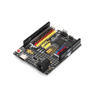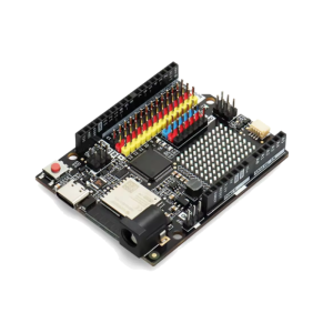
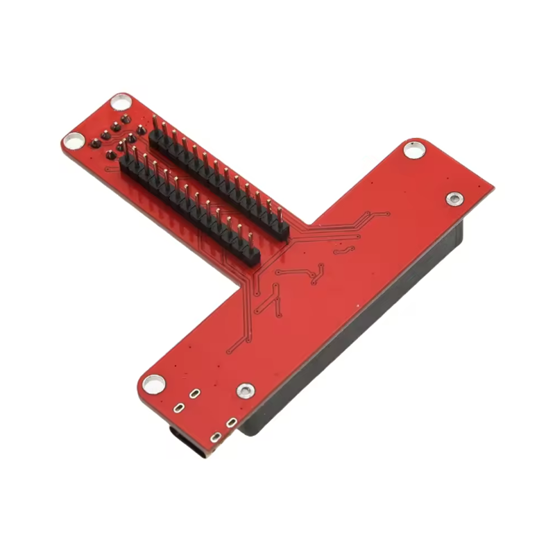
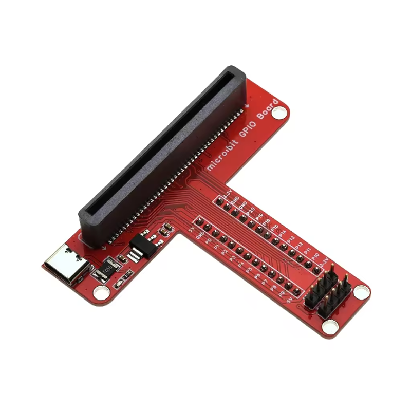
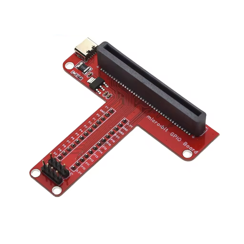
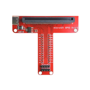
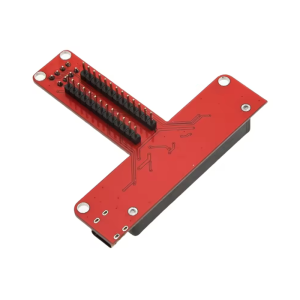
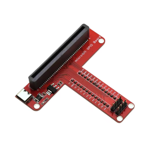
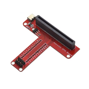
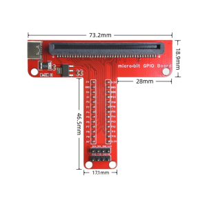
Microbit T-Type GPIO Interface Expansion Board for Microbit V1.5 V2 V2.2 Development Board (Type-C)

SKU: FA1078-5-1
Compatibility

Micro:bit V1.5, V2, V2.2

Interface Type

Edge connector to 0.1″ male headers

GPIO Pins Exposed

P0–P16, P19, P20

Power Pins

3V and GND

Header Pitch

2.54mm (0.1″)

USB Interface

Type-C (for power and programming)

Form Factor

T-shaped, mounts directly on micro:bit

Assembly

Fully assembled, no soldering required

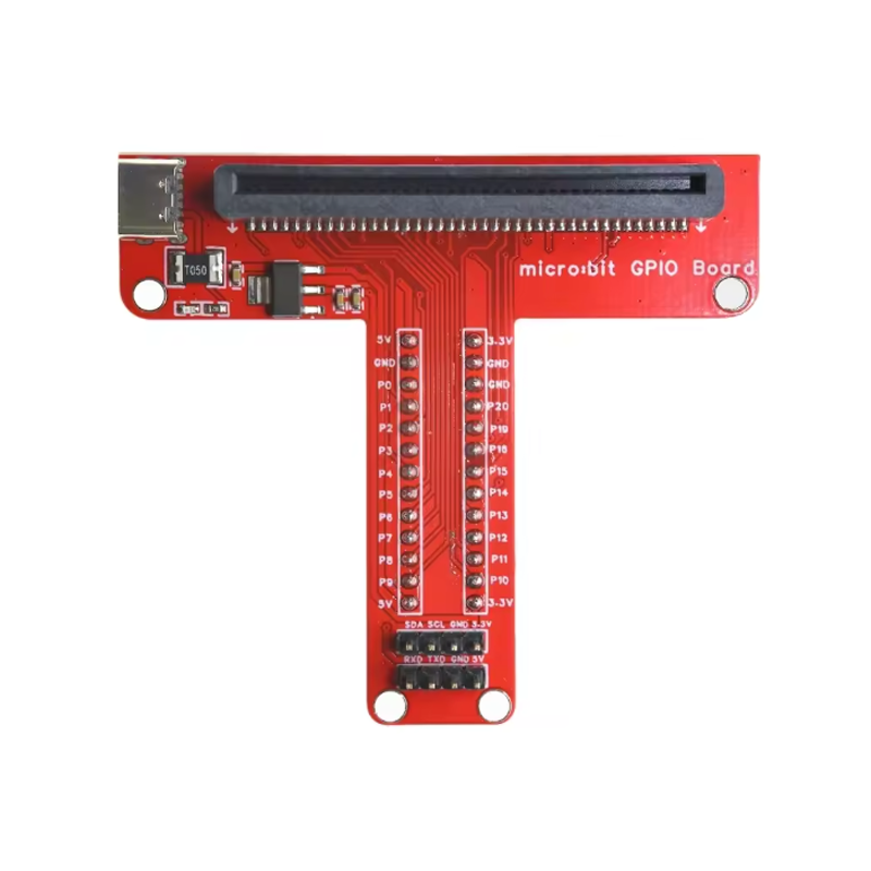
The Micro:bit T-Type GPIO Interface Expansion Board with Type-C interface is a practical breakout adapter designed to make the micro:bit‘s edge connector pins easily accessible for breadboard prototyping, jumper wire connections, and external circuit integration. It transforms the micro:bit’s compact 20-pin edge connector into a convenient T-shaped layout with clearly labeled, standard 0.1-inch pitch headers, while also providing a modern Type-C interface for power and programming.

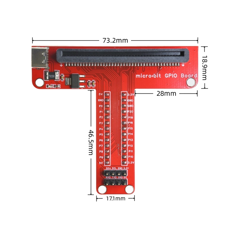
The micro:bit is a powerful and versatile educational platform, but its edge connector requires special connectors or clips to access the GPIO pins. This T-Type expansion board solves that problem by providing a secure, plug-in interface that exposes all available pins — including P0, P1, P2, P3, P4, P5, P6, P7, P8, P9, P10, P11, P12, P13, P14, P15, P16, P19, P20, plus 3V and GND — on easily accessible male headers. This makes it simple to connect sensors, LEDs, motors, and other peripherals without soldering or special adapters.

The Type-C interface is a key feature of this variant. Unlike the standard Micro USB version, this board provides a Type-C connector for power and programming, offering reversible plug orientation and compatibility with the increasingly standard Type-C cables used by modern computers and devices. This makes it a future-proof choice for classrooms, makerspaces, and product development environments where Type-C has become the norm.

The board is compatible with micro:bit V1.5, V2, and V2.2 development boards, ensuring broad compatibility across the most widely used versions of the platform. The T-shaped form factor keeps the board compact and stable when mounted on the micro:bit, and the clearly labeled pins reduce wiring errors — a significant advantage for classroom and educational environments. The board is fully assembled and ready to use, with no soldering or additional components required.

Whether you are a student learning electronics, a teacher preparing classroom kits, or a maker building a complex project, the Micro:bit T-Type GPIO Interface Expansion Board with Type-C provides a reliable, convenient way to unlock the full I/O capabilities of your micro:bit while embracing modern connectivity standards.


Features

  • Full pin breakout — All available micro:bit GPIO pins exposed on standard 0.1″ headers

  • Type-C interface — Modern, reversible connector for power and programming

  • T-shaped form factor — Compact, stable design that mounts securely on the micro:bit

  • Clearly labeled pins — Silkscreen markings reduce wiring errors and speed up assembly

  • Broad compatibility — Works with micro:bit V1.5, V2, and V2.2 development boards

  • No soldering required — Fully assembled and ready to use out of the box

  • Breadboard friendly — Standard header pitch allows direct connection to breadboards and jumper wires

  • Durable construction — Secure edge connector interface for repeated plugging and unplugging


Technical Specifications

# Parameter Specification
1 Compatibility Micro:bit V1.5, V2, V2.2
2 Interface Type Edge connector to 0.1″ male headers
3 GPIO Pins Exposed P0–P16, P19, P20
4 Power Pins 3V and GND
5 Header Pitch 2.54mm (0.1″)
6 USB Interface Type-C (for power and programming)
7 Form Factor T-shaped, mounts directly on micro:bit
8 Assembly Fully assembled, no soldering required

Usage

Getting Started

  1. Attach the expansion board — Align the board‘s edge connector with the micro:bit’s 20-pin edge connector and press firmly to seat. The T-shaped board should sit securely on top of the micro:bit.

  2. Connect power — Power the micro:bit via the Type-C port or a battery pack. The expansion board draws power from the micro:bit‘s 3V rail.

  3. Connect peripherals — Use jumper wires to connect sensors, LEDs, motors, and other components to the labeled GPIO headers. Each header corresponds to a specific micro:bit pin.

  4. Program the micro:bit — Use MakeCode, Python, or JavaScript to write your program, then download it to the micro:bit via the Type-C connection or the mobile app.

  5. Test and iterate — Verify your connections and adjust your code as needed.

Pin Reference

Pin Function
P0, P1, P2 Analog input, touch, large pins
P3, P4, P5, P6, P7, P8, P9, P10 Digital I/O, PWM
P11, P12, P13, P14, P15, P16 Digital I/O, PWM
P19, P20 I2C (SCL, SDA)
3V 3.3V power output
GND Ground

Typical Applications

  • Sensor projects — Connect temperature, humidity, light, and motion sensors

  • Motor and servo control — Drive motors and servos with external power

  • LED and display projects — Control LED strips, matrices, and displays

  • Robotics — Build complex robotic systems with multiple peripherals

  • Classroom and STEM education — Simplifies wiring for student projects

  • Prototyping — Rapid iteration with breadboard-compatible headers

Notes for Business Buyers

  • Type-C advantage — Modern, reversible connector aligns with current device standards and reduces cable compatibility issues

  • Classroom-ready — Clearly labeled pins and no-soldering design reduce setup time for educational environments

  • Broad compatibility — Works with all major micro:bit versions, simplifying inventory management

  • Suitable for bulk purchasing — Ideal for schools, training centers, and educational programs

Q: Is this expansion board compatible with all micro:bit versions?

Yes. It is compatible with micro:bit V1.5, V2, and V2.2 development boards.

Q: What is the difference between this Type-C version and the Micro USB version?

The Type-C version uses a modern, reversible Type-C connector for power and programming, while the Micro USB version uses the older Micro USB standard. Both offer the same GPIO breakout functionality.

Q: Do I need to solder anything to use this board?

No. The board is fully assembled and ready to use. Simply plug it onto the micro:bit‘s edge connector.

Q: What pins are exposed on this expansion board?

The board exposes P0–P16, P19, P20, plus 3V and GND power pins.

Q: Can I use this board with a breadboard?

Yes. The standard 0.1″ (2.54mm) header pitch allows direct connection to breadboards and jumper wires.

Q: Does the Type-C port power the micro:bit?

Yes. The Type-C port provides power to the micro:bit and also supports programming via the appropriate software.

Q: Can I power external components from this board?

Yes. The board provides access to the micro:bit’s 3V and GND pins, allowing you to power low-current external components. For high-current devices like motors, use an external power supply.

Q: Is this board suitable for beginners?

Yes. The clearly labeled pins and no-soldering design make it particularly well suited for beginners and educational settings.

Q: Can I use multiple expansion boards at the same time?

No. The board mounts directly onto the micro:bit‘s edge connector, so only one expansion board can be used at a time.

Q: Can I purchase in bulk for a school or training program?

Yes. This expansion board is suitable for both individual users and business purchasing, including classroom sets, training centers, and educational programs.