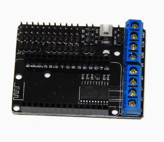
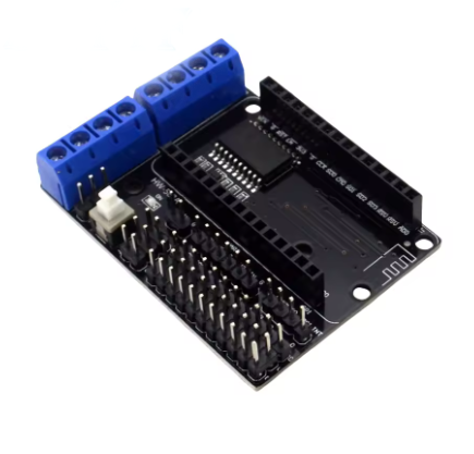
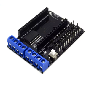
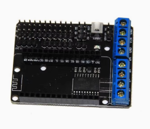
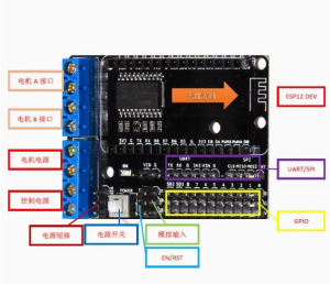
The ESP8266 WiFi Motor Driver Expansion Board is a highly integrated IoT solution that merges the powerful ESP-12E microcontroller with a reliable L293D Dual H-Bridge motor driver shield on a single compact PCB. This innovative design allows users to build internet-connected robots, smart cars, or remote automation systems with minimal wiring and complexity.
The on-board ESP-12E module, powered by the ESP8266 chip, provides full WiFi functionality and can be programmed using the Arduino IDE or the Lua-based NodeMCU firmware. The integrated L293D chip offers dual H-bridge motor control, enabling simultaneous management of the direction and speed of two DC motors, or one stepper motor.
This board is a true all-in-one platform for developing IoT robotics projects. It is an excellent choice for hobbyists seeking seamless web control for their creations and businesses looking for a compact, cost-effective R&D platform for connected devices.
Technical Parameters & Specifications
| Parameter |
Detail |
| Microcontroller |
ESP8266 ESP-12E Module (Integrated) |
| Connectivity |
WiFi 802.11 b/g/n (Station/SoftAP/SoftAP+Station modes) |
| Programming Support |
Arduino IDE, NodeMCU (Lua) |
| Motor Driver IC |
L293D Dual H-Bridge |
| Motor Control |
2 DC Motors (Speed & Direction) or 1 Stepper Motor |
| Operating Voltage (System) |
4.5V to 9V DC Input (via standard DC barrel jack or VIN pins) |
| Operating Voltage (Motors) |
Derived from main input voltage (via jumper selection) |
| Max Current per Channel |
600mA Continuous (1.2A Peak) |
| I/O Expansion |
Breaks out ESP8266 GPIO pins for additional sensor connections |
| Dimensions |
Approx. 50mm x 55mm (Compact Smart Car Form Factor) |
This integrated board is specifically designed for Internet of Things (IoT) applications that require mobility or remote actuation.
- IoT Smart Cars/Robots: Build a robot car that can be controlled remotely over a local network or the internet via a web browser or smartphone application.
- Web-Enabled Automation: Create remote-controlled physical systems, such as automated camera mounts, smart feeders, or remote-controlled switch mechanisms.
- STEM/Educational Projects: A powerful platform for teaching concepts that merge hardware programming (robotics) with network programming (WiFi/IoT).
- Commercial R&D & Prototyping (Business Use): Ideal for rapid development of connected devices that require motion control, allowing businesses to quickly validate product concepts before designing custom PCBs.
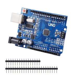
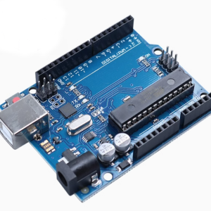
Q: What is the main advantage of this board compared to an Arduino Uno + WiFi Shield + Motor Shield?
Integration and size. Combining all features into one board eliminates messy wiring, reduces the footprint significantly, lowers overall cost, and provides a single, cohesive power management system.
Q: Can I program this using the standard Arduino IDE?
Yes. You must install the ESP8266 board definitions in the Arduino IDE Board Manager. You program it just like any other ESP8266 development board.
Q: What is Lua/NodeMCU support?
The ESP8266 can run NodeMCU firmware, which uses the Lua scripting language. This offers an alternative, often faster, way to develop network applications compared to the standard Arduino C++ environment.
Q: How do I power this board and the motors?
The board accepts a single input voltage (4.5V to 9V DC) via the DC barrel jack or VIN pins. A voltage regulator on the board steps down the voltage for the ESP8266 logic (3.3V). A jumper often exists to route the input voltage directly to the L293D motor driver section.
Q: Can I use a 9V battery?
Yes, a standard 9V battery can power the board for light testing. However, motors draw significant current, and a standard 9V battery may drain very quickly. A 4xAA battery pack or a small LiPo battery is generally recommended for reliable operation.
Q: How many motors can I control?
You can control 2 brushed DC motors (with full forward/reverse/speed control) or 1 bipolar stepper motor.
Q: Which GPIO pins does the L293D use?
The motor driver uses specific GPIO pins of the ESP8266 for control (typically D1, D2, D3, D4, and potentially PWM pins). Specific pin mapping can vary slightly between manufacturers, but they are usually clearly marked on the silkscreen of the PCB. Ensure you don’t use these assigned pins for other sensors in your code.
Q: (For Business Users) Are bulk discounts available?
Please contact our sales or procurement department directly to discuss tiered pricing and logistics for bulk B2B purchases of this module.