GY-25A SCA60C Dual-Axis Tilt Sensor Module – High-Precision Analog/Serial Inclinometer for Angle Measurement & Detection

SKU: FA2012-2-1
Model Number

GY-25A

Power Supply Voltage

3.3V – 5V DC

Output Type

Analog Voltage & Serial Port (UART)

X-axis Output Range

0V – 3.3V (corresponds to ±180 degrees)

Y-axis Output Range

0V – 3.3V (corresponds to ±90 degrees)

Resolution

0.01 degrees (via serial communication)

Frequency Response

100 Hz (at 115200 bps baud rate)

Baud Rates Supported

9600 bps or 115200 bps (selectable via solder jumper)

Module Dimensions

15 mm x 13.3 mm

The GY-25A SCA60C Dual-Axis Tilt Sensor Module is a high-precision inclination detection module offering flexible analog and serial communication outputs, making it ideal for various angle measurement projects in robotics, automation, and industrial monitoring. It serves as a direct replacement for the original SCA60C sensor module while offering enhanced integration capabilities.
Product Description
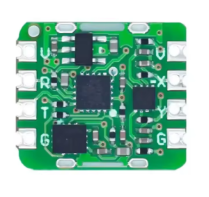
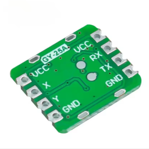
The GY-25A SCA60C Dual-Axis Tilt Sensor Module provides a compact and versatile solution for accurately measuring tilt angles along the X and Y axes. Designed as an effective replacement for the legacy SCA60C, this module simplifies the process of integrating precise tilt detection into electronic projects. It operates on a wide 3.3V to 5V power supply, making it compatible with most standard microcontrollers like Arduino and Raspberry Pi.
A key advantage of the GY-25A is its dual output capability: it provides dedicated analog voltage pins for immediate readings and also supports serial (UART) communication for potentially higher precision digital data or more structured information. The module is capable of dynamic inclination measurement, ensuring reliable performance even when the orientation changes frequently. Its small physical size is advantageous for space-constrained applications, and it features multiple mounting holes for secure installation. This balance of performance, ease of use, and durability makes it suitable for both hobbyist use and professional product development.
Key Features
  • High-Precision Dual-Axis Measurement: Measures tilt along both X and Y axes with high accuracy.
  • Dual Output Modes: Offers both analog voltage output and serial port (UART) communication for versatile integration.
  • Wide Compatibility: Operates on a supply voltage range of 3.3V to 5V, compatible with most microcontrollers.
  • Dynamic Measurement Capability: Suitable for applications involving movement and constant changes in orientation.
  • Compact Form Factor: Small module size (approx. 15mm x 13.3mm) for easy physical integration into designs.
  • SCA60C Replacement: Designed to replace SCA60C modules, offering similar functionality and enhanced precision
Usage
The GY-25A module is commonly used in robotics, automation, and stability control systems.
  1. Power Connection: Connect the VCC pin to a stable 3.3V or 5V source and the GND pin to the system ground.
  2. Analog Output: For simple analog readings, connect the X and Y output pins to the analog input pins (ADC) of your microcontroller. The voltage range is 0V to 3.3V.
  3. Serial Communication: For digital data transmission, connect the module’s TX pin to your microcontroller’s RX pin, and the module’s RX pin to your microcontroller’s TX pin. Configure your microcontroller’s serial port to the correct baud rate (e.g., 9600 or 115200 bps).
  4. Mounting: Securely mount the module using the provided holes, ensuring the orientation is correct for your required measurements
Q: What is the difference between the analog and serial output?

The analog output provides a continuous voltage that needs to be read and converted to an angle in your software. The serial output sends formatted digital angle data directly, often with higher resolution (0.01°).

Q: Does this sensor work dynamically (while moving)?

Yes, the GY-25A supports dynamic inclination measurement, making it suitable for moving applications like self-balancing robots and crane monitoring systems.

Q: Is calibration needed?

For basic use, the factory settings are often sufficient. For high-precision applications, especially after mounting, software calibration may be necessary to compensate for physical offsets.

Q: Can I use this with a Raspberry Pi which uses 3.3V logic?

Yes, the module is compatible with 3.3V systems. Connect VCC to the 3.3V rail on the Raspberry Pi.

Q: How do I select the baud rate for serial communication?

The baud rate is typically selected via a solder jumper on the PCB, allowing you to choose between standard rates like 9600 bps and 115200 bps.