Product Overview
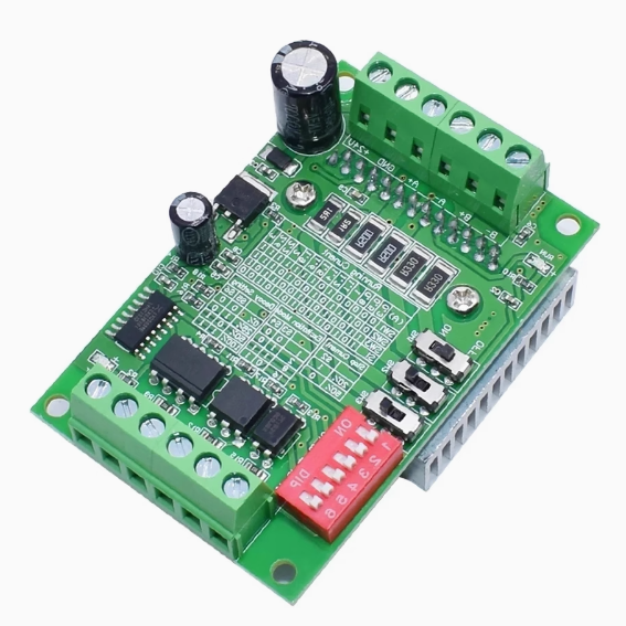
The TB6560 3A Stepper Motor Driver Board is a high-performance, single-axis controller designed for precision motion control in CNC machinery, 3D printers, robotics, and industrial automation. Built around the advanced Toshiba TB6560AHQ chip , this driver represents a significant upgrade from basic driver modules, offering a unique combination of high current output, flexible microstepping, and sophisticated current control features .
Unlike simpler drivers, the TB6560 incorporates Toshiba’s proprietary Selectable Mixed Decay Mode (SMDM) technology, which allows you to adjust the coil discharge pattern to match your specific motor and application . This results in minimized PWM ripple, reduced audible noise, and virtually eliminated vibration—addressing the common issues of resonance and mechanical shake that plague standard stepper drivers .
With a maximum output current of 3.5A peak (3A continuous) and support for a wide input voltage range of 10V to 35V DC , this driver is capable of powering a diverse range of stepper motors, from small NEMA 17 to larger NEMA 23 and even some NEMA 34 frame sizes . The inclusion of a large aluminum heatsink ensures reliable operation even under sustained high-current loads .
Whether you are retrofitting a CNC router, building a custom engraving machine, or developing precision automation equipment, the TB6560 provides the professional-grade features and robust performance required for demanding applications.
Key Features
-
Toshiba TB6560AHQ Chipset: Powered by the advanced Toshiba TB6560AHQ motor driver IC, a high-performance, single-chip PWM chopper-type sinusoidal micro-step bipolar stepping motor driver .
-
High Output Current: Delivers a maximum rated output current of 3A continuous (3.5A peak), providing ample power for a wide range of 2/4-phase stepper motors, including 42mm, 57mm, and 86mm frame sizes .
-
Wide Operating Voltage: Accepts input voltage from 10V to 35V DC . The broad voltage range allows for optimization of high-speed torque (higher voltage) while maintaining compatibility with various power supplies. Recommended voltage selection: 12-16V for NEMA 17, 16-24V for NEMA 23, 24-36V for NEMA 34 motors .
-
10-Speed Microstep Adjustment: Offers selectable excitation modes to balance smoothness, resolution, and speed. Configurable via DIP switches to:
-
Full Step (1/1): Maximum speed, lowest resolution .
-
Half Step (1/2): Improved smoothness .
-
1/8 Step: High smoothness for most applications .
-
1/16 Step: Maximum smoothness and highest resolution, ideal for precision work .
-
Adjustable Drive Current (8 Settings): Features precise current control with 8 selectable settings via DIP switches (typically 0.3A, 0.5A, 0.8A, 1A, 1.1A, 1.2A, 1.4A, 1.5A, 1.6A, 1.9A, 2A, 2.2A, 2.6A, 3A, depending on the board variant) . This allows you to perfectly match the driver output to your motor’s rated current, preventing overheating .
-
Selectable Mixed Decay Mode (SMDM): A sophisticated feature that allows adjustment of the coil current decay pattern (0%, 25%, 50%, 100%) via DIP switches . This helps to:
-
Eliminate motor noise and vibration when locked .
-
Reduce shaking during motor movement .
-
Match the driver impedance to different motors for optimal performance .
-
Automatic Half-Current (Idle Current Reduction): Features a programmable idle current reduction function (Torque Settings) that reduces motor current to 20%, 50%, 75%, or 100% of the operating current when no pulse signal is received . This significantly reduces motor and driver heating during idle periods while maintaining holding torque .
-
High-Speed Optocoupler Isolation: Utilizes high-speed optocouplers (such as 6N137) on all control signal inputs (CLK, CW, ENABLE) . This ensures:
-
Excellent noise immunity in electrically noisy environments.
-
Protection of your CNC controller or computer from back-EMF and voltage spikes.
-
High-speed signal transmission without losing steps .
-
Comprehensive Protection Features:
-
Over-temperature Protection: Built-in thermal shutdown (typically 150°C) automatically disables outputs to prevent damage .
-
Over-current Protection: Safeguards the driver and motor against excessive current draw .
-
Low-Voltage Protection: Prevents erratic operation under low-voltage conditions .
-
Large Passive Heatsink: Comes with a substantial aluminum heatsink to ensure efficient heat dissipation during continuous high-current operation, enhancing long-term reliability .
-
Universal Motor Compatibility: Designed for 2-phase and 4-phase hybrid stepper motors, compatible with 4, 6, or 8 wire configurations (bipolar and unipolar) .
Technical Specifications
Pinout & Interface Guide
Power Terminals
Motor Output Terminals
-
A+, A-: Connect to Phase A of your stepper motor.
-
B+, B-: Connect to Phase B of your stepper motor.
Identifying Motor Wires: Use a multimeter in continuity mode. Wires from the same coil will be continuous (show low resistance). Connect one coil to A+/A- and the other to B+/B- . If the motor rotates in the wrong direction, swap the wires on either A+/A- or B+/B- (not both).
Control Signal Terminals
These terminals are optically isolated. They accept signals from your motion controller (e.g., Arduino, parallel port breakout board, PLC).
-
CLK+ / CLK- (Step Pulse): The step pulse input. Each pulse (typically a 5V signal) advances the motor by one step or microstep, depending on the excitation mode setting . The maximum recommended frequency is typically 15-20 kHz .
-
CW+ / CW- (Direction): The direction control input. A logic high or low on this pin determines the motor’s rotation direction (clockwise or counter-clockwise) .
-
EN+ / EN- (Enable): The enable input. When this signal is active (typically grounded), the driver outputs are enabled, and the motor holds position. When inactive (open or high), the driver outputs are disabled, and the motor enters a “free” state (no holding torque) .
Wiring Example: For common anode connection with a 5V controller, connect CLK+, CW+, and EN+ together to the controller’s +5V. Connect CLK-, CW-, and EN- to the respective output pins of your controller .
Status Indicators
DIP Switch Configuration (SW1 – SW4 or more)
The TB6560 board typically features a set of DIP switches for configuring current, decay mode, microstepping, and idle current reduction. Configure switches with power OFF . The exact labeling and number of switches may vary by manufacturer; always refer to the silkscreen on your specific board.
Common Configuration Functions:
Current Setting (e.g., SW1, SW2, SW3): These switches set the output current to match your motor’s rated current. A typical configuration table might look like this:
Decay Mode Setting (e.g., SW4, SW5): These switches adjust the current decay mode to match your motor’s characteristics and eliminate noise/vibration .
-
0%: No decay mode
-
25%: Slow decay mode
-
50%: Normal mode
-
100%: Fast decay mode
Excitation Mode / Microstep Setting (e.g., SW6, SW7): These switches select the microstep resolution.
Idle Current Reduction / Torque Setting (e.g., SW8, SW9): These switches set the hold current as a percentage of the running current .
Usage Guide
Important Safety Warnings
-
Never connect or disconnect motor wires while the driver is powered on. Doing so generates high-voltage spikes that will permanently damage the driver.
-
Ensure power supply voltage does not exceed the maximum rating of 35V DC . Over-voltage is a common cause of driver failure.
-
Use a power supply with sufficient current capacity. For a single axis, a 24V 5A supply is a good starting point for most NEMA 23 motors .
-
Ensure proper grounding to minimize electrical noise interference.
-
Do not operate without the heatsink or in an enclosed space without adequate ventilation.
First-Time Setup Procedure
-
Configure DIP switches for your motor’s rated current, desired microstep resolution, decay mode, and idle current reduction with power OFF .
-
Connect motor to A+/A- and B+/B- terminals.
-
Connect power supply (e.g., 24V DC) to VCC and GND.
-
Connect control signals (CLK, CW, EN) to your controller (e.g., Arduino, parallel port).
-
Apply power – the power LED should illuminate.
-
Test operation with simple step/direction signals at a low speed.
-
Check motor temperature after a few minutes of operation. If the motor is excessively hot, reduce the current setting or adjust the idle current reduction .
Voltage Selection Guidelines
Choose your power supply voltage based on your motor size :
-
NEMA 17: 12V – 16V DC
-
NEMA 23: 16V – 24V DC
-
NEMA 34: 24V – 36V DC
Basic Arduino Example Code
This code will make the motor rotate forward and reverse continuously.
int CLK = 7;
int CW = 6;
int EN = 5;
void setup() {
pinMode(CLK, OUTPUT);
pinMode(CW, OUTPUT);
pinMode(EN, OUTPUT);
digitalWrite(EN, LOW);
}
void loop() {
digitalWrite(CW, HIGH);
for(int i = 0; i < 1600; i++) {
digitalWrite(CLK, HIGH);
delayMicroseconds(500);
digitalWrite(CLK, LOW);
delayMicroseconds(500);
}
delay(1000);
digitalWrite(CW, LOW);
for(int i = 0; i < 1600; i++) {
digitalWrite(CLK, HIGH);
delayMicroseconds(500);
digitalWrite(CLK, LOW);
delayMicroseconds(500);
}
delay(1000);
}
Q: What is the TB6560 driver and what makes it special?
The TB6560 is a stepper motor driver based on the Toshiba TB6560AHQ chip . Its special features include Selectable Mixed Decay Mode (SMDM) , which allows you to tune the driver to eliminate motor noise and vibration, and comprehensive idle current reduction settings to minimize heat generation
Q: What types of motors can I use with the TB6560?
It is designed for 2-phase and 4-phase hybrid stepper motors with a maximum current of 3A. It is compatible with 4, 6, or 8 wire configurations (bipolar and unipolar) and is commonly used with NEMA 17, 23, and smaller NEMA 34 motors
Q: What is the maximum current this driver can provide?
The driver has a maximum rated output current of 3A continuous and can handle 3.5A peak . You must set the current via DIP switches to match your motor’s rated current
Q: Can I use this with a 3.3V controller like an ESP32 or Raspberry Pi?
The logic inputs are optically isolated and typically designed for 5V-24V signals . While you can try using 3.3V signals, they may not reliably trigger the optocouplers. We recommend using a small level shifter or configuring the driver for common anode wiring with a 5V pull-up for guaranteed reliability.
Q: How do I set the output current correctly?
Use the DIP switches designated for current setting (e.g., SW1, SW2, SW3). You must set the current to a value equal to or less than your motor’s rated current . Consult your motor datasheet and refer to the current table printed on your specific driver board. Start with a lower setting and monitor motor temperature
Q: What is Decay Mode and how do I set it?
Decay Mode controls how the current in the motor coils is reduced during PWM switching . Incorrect settings can cause noise and vibration. Start with the 50% (Normal) setting. If your motor vibrates excessively or makes noise when locked, try the 25% or 0% settings. The 100% (Fast Decay) setting is rarely needed
Q: What microstep setting should I choose?
The optimal setting depends on your application:
-
1/1 (Full step): Highest speed, but more vibration. Suitable for high-speed applications where smoothness isn’t critical.
-
1/2 (Half step): A basic improvement in smoothness.
-
1/8 Step: A good all-around setting for most CNC and 3D printer applications, balancing smoothness and speed .
-
1/16 Step: Smoothest operation and highest resolution, ideal for precision work like PCB drilling or fine engraving
Q: What is Idle Current Reduction (Torque Setting)?
This feature reduces the current flowing to the motor when it’s idle (not receiving step pulses) . This significantly reduces heat buildup in both the motor and the driver while still maintaining some holding torque. A setting of 50% is a good starting point for most applications
Q: What power supply should I use?
Select a power supply based on your motor :
-
Voltage: 12-36V DC, depending on your motor size. Higher voltage generally improves high-speed torque.
-
Current: The power supply should be rated for at least the total current draw of all your motors plus a safety margin. A common formula is: Power supply current = (Motor rated current × Number of motors) + 2A
Q: My motor is weak or lacks torque. What could be wrong?
Common causes and solutions:
-
Insufficient voltage: Use a higher voltage supply (up to 36V) for better high-speed torque.
-
Current too low: Verify DIP switches are set to the correct current for your motor.
-
Power supply inadequate: Ensure your supply can deliver enough current without voltage sag.
-
Decay mode incorrect: Try adjusting the decay mode settings
Q: The motor gets very hot. Is this normal?
Some warmth is normal, but excessive heat indicates:
-
Current set too high: Reduce the current setting to match your motor’s rating .
-
Idle current reduction not enabled: Configure the DIP switches to reduce current when idle (e.g., 50% setting) .
-
Motor undersized: The motor may be too small for the application load.
Q: The motor makes a loud noise or vibrates excessively.
This is often a resonance issue that the TB6560 is designed to fix . Try:
-
Adjusting the Decay Mode DIP switches to find the optimal setting for your motor .
-
Changing the Microstep setting (e.g., from 1/8 to 1/16) .
-
Ensuring your power supply voltage is stable.
Q: The motor doesn't move at all. What should I check?
Follow this systematic checklist:
-
Power OK? Power LED should be on. Check power supply connections and voltage.
-
Enable signal? If using EN, ensure it’s set to enable the driver (typically active LOW). If not using EN, ensure EN+ is not grounded .
-
Motor connected? Verify motor wires are securely connected to A+/A- and B+/B-.
-
Pulse signal? Check with an LED or oscilloscope that pulses are reaching the CLK input. The signal LED should flash .
-
Current setting? Verify DIP switches are set correctly for your motor.
Q: The driver works initially but stops after a few minutes.
This is classic thermal shutdown behavior :
Q: The motor runs in the wrong direction.
This is easily fixed by either:
Q: The motor runs slowly or seems to be missing steps.
The TB6560 has a limited maximum step pulse frequency (typically 15-20 kHz) . If you are using a high microstep setting (like 1/16) and trying to run at a high speed, you may be exceeding this limit. Try reducing the microstep setting or lowering the target speed.
Q: I'm using this with Marlin firmware and the movement is extremely slow.
This can occur if the wrong driver type is selected in the firmware. Ensure that in your Configuration.h file, you have set the driver type to TB6560. Some users have reported issues with very slow movement when using the TB6560 setting in the latest Marlin versions . If you encounter this, try using the A4988 setting instead, but be aware this may cause other issues.