Product Overview
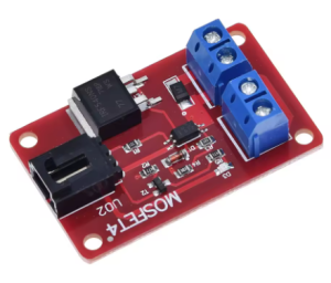
The High Power IRF540 MOSFET Module is a robust and reliable solid-state switch designed to bridge the gap between low-voltage microcontrollers and high-power DC loads. At its core is the legendary IRF540 N-Channel Power MOSFET , a component renowned in the electronics industry for its excellent switching characteristics, high current capability, and rugged design .
This module provides a complete, ready-to-use solution for controlling high-power DC devices such as motors, solenoids, high-intensity LEDs, pumps, and industrial actuators. A key feature of this module is the inclusion of optical isolation between the low-voltage control side (your Arduino, Raspberry Pi, ESP32, or PLC) and the high-power load side . This galvanic isolation protects your sensitive and expensive control electronics from dangerous voltage spikes, back-EMF from motors, and ground loop interference, ensuring stable and safe operation even in electrically noisy environments .
With the ability to switch DC loads up to 100V at 33A (with appropriate thermal management) , this module is the ideal choice for demanding projects where safety and reliability are paramount. Its simple 3-pin interface makes it incredibly easy to integrate, turning any digital pin or PWM output into a powerful high-current driver .
Key Features
-
Powerful IRF540 N-Channel MOSFET: Built around the industry-standard IRF540, a MOSFET known for its low on-resistance (RDS(on) ≤ 0.077Ω) and robust construction, ensuring efficient power delivery and minimal heat generation .
-
High Voltage & Current Handling: Capable of switching DC loads with voltages up to 100V and continuous currents up to 33A (with proper heatsinking) . This makes it suitable for a vast array of high-power 12V, 24V, 48V, and even 72V DC systems.
-
Opto-Isolated Control Input: Features optical isolation between the input signal terminals and the power circuit . This crucial feature protects your microcontroller from back-EMF, voltage spikes, and electrical noise generated by inductive loads like motors and solenoids .
-
Simple 3-Pin Control Interface: The module uses a straightforward 3-pin header for control, compatible with 3.3V and 5V logic levels from devices like Arduino, Raspberry Pi, ESP32, and PLCs .
-
PWM Compatible for Analog Control: The high-speed switching capability of the IRF540 allows it to accept Pulse Width Modulation (PWM) signals . This enables smooth speed control of DC motors or stepless dimming of LED lighting, going far beyond simple on/off switching.
-
Visual Status Indicator: An onboard LED provides a clear, real-time visual indication of when the MOSFET is switched on, simplifying troubleshooting and operation monitoring .
-
Robust Screw Terminals: Equipped with heavy-duty screw terminals for secure and reliable connections to your high-power load and external power supply.
-
Wide Application Range: Perfect for a variety of DC power control tasks, including motor speed control, LED dimming, solenoid and relay driving, pump control, and as a general-purpose high-current switch in industrial and DIY automation projects .
Technical Specifications
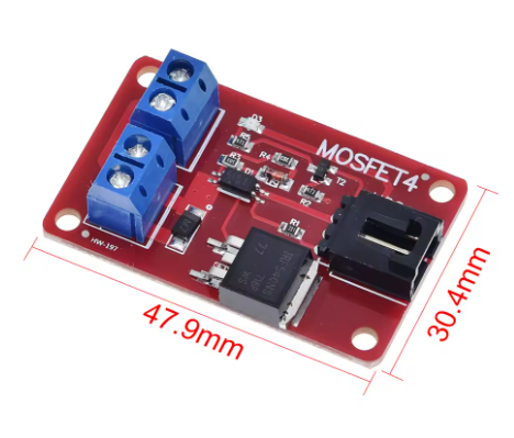
Pinout & Interface Guide
The module is clearly divided into a low-voltage control side and a high-voltage power side.
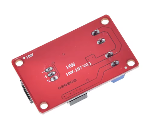
Control Side (3-Pin Header)
-
SIG (Signal): The control pin. Apply a HIGH logic signal (3.3V-5V) to turn the MOSFET ON and a LOW signal (0V) to turn it OFF . Sending a PWM signal here allows for speed or brightness control .
-
VCC (+5V): Powers the internal optocoupler circuitry. Connect to your microcontroller’s 3.3V or 5V output.
-
GND (Ground): Common ground for the control side. Connect to a GND pin on your microcontroller.
Power Side (Screw Terminals)
-
**V+ (or + ): ** The positive input for your external DC power supply (9-100V). Connect the positive lead from your battery or power supply here .
-
**V- (or – ): ** The negative input for your external DC power supply. Connect the negative (ground) lead from your power supply here.
-
**OUT (or Motor – ): ** The switched output. Connect the negative wire of your load (motor, LED strip, etc.) to this terminal. The MOSFET acts as a switch between this terminal and the power supply ground. The load’s positive wire should be connected directly to the positive terminal of your external power supply.
Usage Guide
Important Safety Warnings
-
DC ONLY: This module is designed strictly for DC circuits . Never connect AC mains power (e.g., household 110V/220V AC) to this module. It will be destroyed instantly and poses a serious safety hazard.
-
Inductive Loads: When controlling inductive loads like motors, solenoids, or pumps, an external flyback (snubber) diode is highly recommended across the load’s terminals (cathode/banded end to load positive, anode to load negative) to absorb voltage spikes and protect the MOSFET, even if the module has some built-in protection .
-
Heatsinking: While the IRF540 can theoretically handle 33A, at high currents it will generate significant heat. For continuous operation above 5-10A, a heatsink is absolutely required to prevent thermal damage.
-
Voltage Limits: Do not exceed the maximum load voltage of 100V DC on the power side .
Wiring Guide (Controlling a 12V DC Motor with an Arduino)
Basic Arduino Example Code
This code demonstrates both simple on/off control and PWM speed control.
int mosfetPin = 9;
int speed = 0;
void setup() {
pinMode(mosfetPin, OUTPUT);
}
void loop() {
digitalWrite(mosfetPin, HIGH);
delay(2000);
digitalWrite(mosfetPin, LOW);
delay(2000);
for (speed = 0; speed <= 255; speed++) {
analogWrite(mosfetPin, speed);
delay(10);
}
for (speed = 255; speed >= 0; speed--) {
analogWrite(mosfetPin, speed);
delay(10);
}
delay(1000);
}
Q: What is the main advantage of an isolated MOSFET module over a non-isolated one?
The key advantage is safety. The optical isolation creates a complete electrical barrier between your expensive and sensitive microcontroller (e.g., Arduino, Raspberry Pi) and the high-power, potentially noisy load circuit . This protects your controller from dangerous voltage spikes (back-EMF) generated by motors and solenoids, and eliminates ground loop problems
Q: What types of loads can I control with this module?
You can control a wide variety of DC loads up to 100V, including:
-
DC motors (for speed control via PWM)
-
High-power LED strips and lighting (for dimming)
-
Solenoid valves and relays
-
DC pumps and fans
-
Other DC-powered actuators and devices
Q: Can this module control AC loads (like a household appliance)?
No, absolutely not. This module is strictly for DC circuits only . It is not designed or safe for AC mains voltage.
Q: Can I use this module with a 3.3V logic controller like a Raspberry Pi or ESP32?
Yes. The control side (SIG and VCC) accepts both 3.3V and 5V logic levels, making it directly compatible
Q: What is the real-world current limit for this module?
While the IRF540 MOSFET itself can handle up to 33A , the practical, continuous current is limited by the module’s PCB design, terminal blocks, and especially the lack of a heatsink. For reliable, continuous operation, it’s wise to stay within 5A to 10A per channel. For short bursts or with a large, externally attached heatsink, you can push higher.
Q: Do I need a flyback diode for my motor?
Highly recommended. When switching any inductive load like a motor or solenoid, the collapse of the magnetic field generates a high-voltage spike that can damage the MOSFET . While the IRF540 has a built-in avalanche diode for some protection , adding an external fast-recovery diode (like a 1N400x or UF400x) across the motor’s terminals is a best practice for long-term reliability. Connect the diode with the cathode (banded end) to the motor’s positive supply and the anode to the motor’s negative.
Q: The module gets hot. Is this normal?
Some heat is normal when switching high currents. The IRF540 has a low on-resistance, but at 5A, it will still dissipate several watts. If the MOSFET is too hot to touch, you need better cooling. Attaching a heatsink to the metal tab of the MOSFET is essential for high-current applications.
Q: The status LED lights up, but my load doesn't turn on.
This is usually a wiring issue with the load side. Remember, this N-Channel MOSFET switches the ground (negative) side of the circuit.
-
Check Load Wiring: Ensure the positive (+) of your load goes directly to the positive (+) of your external power supply.
-
Check Module Wiring: Ensure the negative (-) of your load goes to the OUT terminal of the module.
-
Check Ground: Ensure the GND of your external power supply is connected to the V- terminal on the module. This completes the circuit through the MOSFET.
Q: The load stays on even when the control signal is set to LOW.
This indicates the MOSFET is not fully turning off. The most common cause is that the gate charge is not being drained. Ensure your microcontroller pin is configured as an OUTPUT and is being driven firmly to LOW (0V) . A failing optocoupler or a shorted MOSFET could also cause this.
Q: My PWM control is jerky or the motor makes a loud noise.
This is often a frequency issue. Try lowering the PWM frequency in your code. Different motors and loads respond best to different frequencies. Experiment with values from a few hundred Hz to a few kHz for optimal performance.