Product Overview
The FR120N Isolation MOSFET Power Module is a sophisticated solid-state switching solution designed to replace traditional mechanical relays in modern electronics. Based on the powerful FR120N N-Channel MOSFET , this module provides a fast, silent, and highly reliable interface between your low-voltage microcontroller (Arduino, Raspberry Pi, ESP32, STM32) and high-power DC loads .
Unlike mechanical relays that rely on physical contacts and electromagnetic coils, this module uses semiconductor technology to achieve high-speed switching with optical isolation . The built-in optocoupler creates a complete electrical barrier between the control side (your sensitive microcontroller) and the high-power load side, protecting your control electronics from dangerous voltage spikes, back-EMF, and electrical noise .
The FR120N MOSFET itself is a robust power transistor capable of handling up to 100V and 15A continuously (with proper cooling), with a low on-resistance of just 0.114Ω that minimizes power loss and heat generation . This makes it an ideal choice for applications requiring efficient, high-speed switching of DC loads such as motors, solenoids, LED lighting, pumps, and industrial actuators .
This module serves as a superior alternative to relays in applications where:
-
High switching speed is required (PWM control)
-
Silent operation is necessary (no mechanical clicking)
-
Long-term reliability is critical (no contacts to wear out)
-
Precise analog control is needed (dimming, speed control)
Key Features
-
Powerful FR120N N-Channel MOSFET: Built around the high-performance FR120N MOSFET, featuring low on-resistance (RDS(on) ≤ 0.114Ω) and excellent switching characteristics for efficient power delivery .
-
High Voltage & Current Capacity: Capable of switching DC loads with voltages up to 100V and continuous currents up to 15A (with adequate heatsinking). Peak pulse current can reach up to 40A for short durations .
-
Opto-Isolated Control Input: Features an optocoupler that provides galvanic isolation between the control signal and the power circuit . This critical feature:
-
Protects your microcontroller from back-EMF and voltage spikes
-
Eliminates ground loop interference
-
Enhances noise immunity in industrial environments
-
Wide Logic Voltage Compatibility: Accepts control signals from 2.5V to 20V , making it directly compatible with both 3.3V microcontrollers (ESP32, Raspberry Pi Pico) and 5V systems (Arduino), as well as 12V-24V industrial PLCs .
-
PWM Compatible for Analog Control: Supports high-speed PWM signals for smooth and efficient speed control of DC motors or stepless dimming of LED lighting, far exceeding the capabilities of mechanical relays .
-
Active HIGH Logic: Simple control interface—apply a HIGH signal (logic 1) to turn the MOSFET ON and connect the load; apply a LOW signal (logic 0) to turn it OFF .
-
Compact and Modular Design: Small footprint (approximately 34mm x 16mm) with mounting holes for easy integration into projects and enclosures. The 0.1″ pin spacing allows direct use with breadboards .
-
Versatile Connection Options: Features solderable terminals and header pins for both signal and power connections, allowing for flexible wiring with screw terminals or direct soldering .
-
Wide Operating Temperature: Engineered for reliability in demanding environments with an operating temperature range of -55°C to +175°C .
Technical Specifications
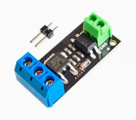
Pinout & Interface Guide
The module is clearly divided into a low-voltage control side and a high-voltage power side.
Control Side (2-Pin Header)
-
PWM / SIG (Signal): The control input. Apply a HIGH logic signal (2.5V-20V) to turn the MOSFET ON. Apply LOW (0V) to turn it OFF . Sending a PWM signal enables speed or brightness control .
-
GND (Ground): Common ground for the control side. Connect to a GND pin on your microcontroller. Note: Due to optoisolation, this ground is electrically isolated from the load ground .
Power Side (3-Pin Screw Terminal)
-
+ (Positive Input): The positive input for your external DC power supply (up to 100V). Connect the positive lead from your battery or power supply here .
-
LOAD (Switched Output): The switched output. Connect the negative wire of your load (motor, LED strip, etc.) to this terminal. The MOSFET acts as a switch between this terminal and the power supply ground .
-
– (Negative Input): The negative input for your external DC power supply. Connect the negative (ground) lead from your power supply here .
Important Wiring Note: The positive wire of your load must be connected directly to the + terminal of your external power supply (or to the same positive source). The module switches the ground (negative) side of the circuit .
Usage Guide
Important Safety Warnings
-
DC ONLY: This module is designed strictly for DC circuits . Never connect AC mains power (e.g., household 110V/220V AC) to this module. It will be destroyed instantly and poses a serious safety hazard.
-
Inductive Loads: When controlling inductive loads like motors, solenoids, or pumps, an external flyback (snubber) diode is required across the load’s terminals (cathode/banded end to load positive, anode to load negative). This protects the MOSFET from voltage spikes generated when the load is switched off .
-
Heatsinking: While the FR120N can handle 15A continuously, at high currents it will generate significant heat. For continuous operation above 5-10A, a heatsink is highly recommended . The module itself has minimal heat dissipation capability .
-
Current Limits: Do not exceed the maximum continuous current rating. Operating at the absolute maximum rating requires proper cooling and is not recommended for extended periods .
-
Parallel Operation: These modules can be connected in parallel to increase power handling capabilities if needed .
Wiring Guide (Controlling a 12V DC Motor with Arduino)
Basic Arduino Example Code
This code demonstrates simple on/off control and PWM speed control.
int mosfetPin = 9;
int speed = 0;
void setup() {
pinMode(mosfetPin, OUTPUT);
}
void loop() {
digitalWrite(mosfetPin, HIGH);
delay(2000);
digitalWrite(mosfetPin, LOW);
delay(2000);
for (speed = 0; speed <= 255; speed++) {
analogWrite(mosfetPin, speed);
delay(10);
}
for (speed = 255; speed >= 0; speed--) {
analogWrite(mosfetPin, speed);
delay(10);
}
delay(1000);
}
Q: What is the advantage of this module over a mechanical relay?
This MOSFET module offers several key advantages over mechanical relays :
-
High-Speed Switching: Can switch on/off thousands of times per second, enabling PWM for speed control and dimming .
-
Silent Operation: No audible “click” sound during switching .
-
Solid-State Reliability: No mechanical contacts to wear out, pit, or weld over time .
-
No Contact Bounce: Clean switching without the electrical noise of relay contact bounce .
Q: What types of loads can I control with this module?
You can control various DC loads up to 100V, including:
-
DC motors (for speed control via PWM)
-
High-power LED strips and lighting (for dimming)
-
Solenoid valves and relays
-
DC pumps and fans
-
Other DC-powered actuators and resistive loads
Q: Can this module control AC loads (like a household appliance)?
No, absolutely not. This module is strictly for DC circuits only . The FR120N is an N-Channel MOSFET designed for DC switching and cannot block AC current .
Q: Can I use this module with a 3.3V controller like a Raspberry Pi or ESP32?
Yes. The control input accepts signals from 2.5V to 20V , making it directly compatible with both 3.3V and 5V logic levels .
Q: What does "optically isolated" mean and why is it important?
Optical isolation means there is no direct electrical connection between the control side (your microcontroller) and the power side (the load). Instead, they communicate via light through an optocoupler. This protects your sensitive and expensive microcontroller from dangerous voltage spikes, back-EMF from motors, and ground loop interference .
Q: What is the real-world current limit for this module?
The FR120N MOSFET itself is rated for 15A continuous current . However, the practical limit depends on cooling. Without a heatsink, it’s wise to stay within 5-8A for continuous operation. With a good heatsink and airflow, you can approach the 15A rating .
Q: Do I need a flyback diode for my motor?
Yes, absolutely required. When switching any inductive load like a motor, solenoid, or pump, the collapse of the magnetic field generates a high-voltage spike that can instantly destroy the MOSFET . An external flyback diode (e.g., 1N4007) connected across the load terminals is essential for long-term reliability .
Q: The module gets hot. Is this normal?
Some heat is normal when switching high currents. The FR120N has a low on-resistance (0.114Ω), so at 10A it will dissipate about 11.4 watts (P = I²R) . This requires a heatsink. If the MOSFET is too hot to touch (>60°C), you need better cooling.
Q: Can I parallel multiple modules for higher current?
Yes. These modules can be connected in parallel to increase the total current handling capacity . Connect all control signals together and all power connections appropriately.
Q: My load doesn't turn on, even though the control signal is HIGH.
Follow this checklist:
-
Check Load Wiring: Remember, the module switches the ground (negative) side. Ensure the load’s positive wire goes directly to the power supply positive, and the load’s negative wire goes to the module’s LOAD terminal .
-
Check Power Supply: Verify your external power supply is on and providing the correct voltage at the + and – terminals .
-
Check Ground Loop: Ensure the control side GND is connected to your microcontroller, and the power side GND is connected to your power supply. They are isolated and should not be connected together .
Q: The load stays on even when the control signal is set to LOW.
This indicates the MOSFET is not fully turning off. Ensure your microcontroller pin is configured as an OUTPUT and is being driven firmly to LOW (0V) . A failing optocoupler or a shorted MOSFET could also cause this.
Q: My PWM control is jerky or the motor makes a loud noise.
This is often a frequency issue. Try lowering the PWM frequency in your code. Experiment with values from a few hundred Hz to a few kHz for optimal performance with your specific motor.
Q: Can I use this module without a microcontroller?
Yes. You can apply a DC voltage (2.5V-20V) directly to the SIG pin to turn the load on. This could come from a sensor, a switch connected to a battery, or any other DC source .