Product Overview
The CCMHCN PWM DC Motor Speed Controller is a high-performance, wide-voltage speed regulation module designed for demanding DC motor applications. Featuring an impressive input voltage range of 6V to 90V DC and a robust current handling capability of 8A continuous (15A maximum) , this controller delivers smooth, efficient, and reliable speed control for a vast array of industrial and hobbyist applications .
Utilizing advanced Pulse Width Modulation (PWM) technology at a 16kHz switching frequency, this controller provides stepless speed adjustment from 0% to 100% duty cycle. The high-frequency PWM ensures quiet motor operation—eliminating the audible whine common with lower-frequency controllers—while maintaining excellent torque even at low speeds .
What sets the CCMHCN apart is its professional-grade versatility. It accepts a wide range of input voltages (6V to 90V), making it compatible with everything from small 6V battery packs to 24V automotive systems and 60V-90V industrial power supplies. With a maximum power handling capability of up to 1000W (at 90V), it can drive pumps, fans, conveyors, power tools, and small electric vehicles with confidence .
The controller also features 0-5V external analog control capability, allowing seamless integration with PLCs (Programmable Logic Controllers), microcontrollers, and industrial automation systems. A built-in 15A fuse provides reliable overload and short-circuit protection, while reverse polarity protection safeguards the module from accidental miswiring .
This controller is the ideal choice for a wide range of applications, including:
-
Industrial Automation: Conveyor systems, production line machinery, packaging equipment
-
PLC Integration: Direct 0-5V control from programmable logic controllers
-
Automotive & Marine: 12V-24V systems, radiator fans, bilge pumps, ventilation fans
-
DIY & Workshop Tools: Bench grinders, drill presses, lathes, dust collectors
-
Renewable Energy: Solar-powered pumps and ventilation systems
-
Small Electric Vehicles: E-bikes, scooters, golf carts (within power limits)
Key Features
-
Ultra-Wide Voltage Range: Accepts DC input from 6V to 90V, providing compatibility with a vast range of power sources including 6V, 12V, 24V, 36V, 48V, 60V, and 90V systems .
-
High Current Capacity: Rated for 8A continuous current with a maximum peak of 15A. A built-in user-replaceable 15A ceramic fuse provides reliable overload protection .
-
High Power Handling: Capable of controlling loads up to 1000W (at 90V), delivering substantial power for demanding applications .
-
Professional PWM Technology: Operates at a 16kHz PWM frequency, ensuring quiet, vibration-free motor operation with smooth speed transitions .
-
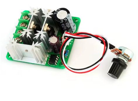
0%-100% Stepless Speed Control: Features a high-quality B10K potentiometer for intuitive, continuous speed adjustment from complete stop to full speed .
-
PLC & External Control Compatible: Supports 0-5V external analog voltage control via dedicated input terminals, enabling seamless integration with PLCs, microcontrollers (Arduino, ESP32), and industrial automation systems .
-
Built-In Protection Features:
-
15A Fast-Blow Ceramic Fuse: User-replaceable 5x20mm fuse for overload and short-circuit protection .
-
Reverse Polarity Protection: Safeguards the controller from accidental reverse connection of the DC power supply .
-
Over-Voltage Protection: Prevents damage from excessive input voltage (built into design specifications).
-
Low Standby Current: Consumes only 0.005A (5mA) in standby mode, minimizing power draw when the motor is not running .
-
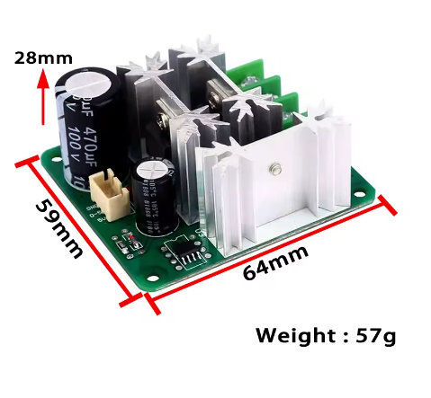
Robust Mechanical Design: Housed in a durable enclosure with mounting holes (3.2mm diameter) for secure installation in control panels or equipment enclosures .
-
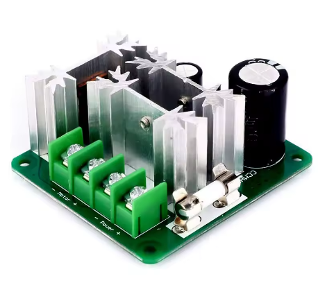
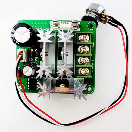
Easy Wiring: Features clearly labeled screw terminals for power input (V+/V-) and motor output (M+/M-), with a convenient 3-pin header for external 0-5V control signals .
Technical Specifications
Pinout & Interface Guide
The controller features clearly labeled screw terminals and a control header for all connections.
Power Terminals
-
V+ / VIN+ (Power Input +): Connect the positive terminal of your DC power source (6V-90V) here. Observe correct polarity—reverse connection can damage the controller .
-
V- / VIN- (Power Input -): Connect the negative terminal (ground) of your DC power source here.
Motor Terminals
-
M+ (Motor Output +): Connect to one wire of your brushed DC motor.
-
M- (Motor Output -): Connect to the other wire of your brushed DC motor.
-
Note: The motor wires are non-polarized. If the motor runs in the wrong direction, simply swap the two wires at the M+ and M- terminals .
Control Interface
-
Onboard Potentiometer: The built-in B10K rotary knob provides manual, stepless speed adjustment from 0% to 100% duty cycle.
-
External Control Header (3-pin): For PLC or microcontroller control:
-
0-5V Pin: Connect the analog control voltage (0-5V) here .
-
GND Pin: Connect the ground of your control signal source here.
-
Note: To use external control, you may need to remove or bypass the onboard potentiometer .
Fuse
Usage Guide
Important Safety Warnings
-
DC ONLY: This controller is designed strictly for DC circuits. Never connect it to AC mains power (e.g., 110V or 220V AC). Doing so will instantly destroy the controller and poses a serious fire hazard .
-
Polarity Matters: Do not reverse the positive and negative terminals of the DC power supply, as this may damage the controller (despite protection features) .
-
Motor Type: This controller is for brushed DC motors only. It is NOT compatible with brushless DC motors (BLDC), stepper motors, or AC motors .
-
Current Limits: The controller is rated for 8A continuous and 15A maximum. Prolonged operation at currents exceeding 8A may cause overheating. The 15A fuse provides protection for overloads and short circuits.
-
Not for LED Strips: This product is not suitable for dimming LED light strips .
Wiring Guide
Step-by-Step Operation
-
Mount the Controller: Secure the module in your enclosure using the 3.2mm mounting holes. Ensure adequate ventilation for high-power operation .
-
Connect the Motor: Connect your brushed DC motor to the M+ and M- terminals. Polarity is not critical for initial testing—if direction is wrong, swap the wires .
-
Connect the Power Supply: Connect your DC power source (6V-90V) to the V+ and V- terminals. Ensure the power supply is turned OFF or disconnected during wiring .
-
Set Initial Speed: Turn the onboard potentiometer knob fully counter-clockwise to its minimum speed position.
-
Apply Power: Turn on your DC power source. The motor should remain off or at very low speed.
-
Adjust Speed: Slowly turn the potentiometer knob clockwise. The motor will begin to spin and increase in speed as you turn. Adjust until you reach the desired speed.
-
Stop the Motor: Turn the knob fully counter-clockwise to return to minimum speed.
-
External Control (PLC): To use PLC or microcontroller control, connect your 0-5V signal to the control header and remove or bypass the onboard potentiometer .
Q: What types of motors can I use with the CCMHCN controller?
This controller is designed for brushed DC motors only operating at 6V to 90V . It is ideal for motors found in pumps, fans, conveyors, power tools, and small electric vehicles. It is not compatible with brushless DC motors (BLDC), stepper motors, or AC motors.
Q: What is the real-world current and power limit?
The controller is rated for 8A continuous current and can handle peak currents up to 15A (protected by the onboard fuse) . The maximum power depends on your input voltage:
-
At 12V: Up to 96W (12V × 8A)
-
At 24V: Up to 192W (24V × 8A)
-
At 90V: Up to 720W (90V × 8A), with an absolute maximum of 1000W
For sustained operation, it is recommended to stay within the 8A continuous rating.
Q: Can I use this controller with a 24V battery or 60V industrial supply?
Yes. The controller accepts any DC voltage from 6V to 90V, making it compatible with 12V, 24V, 36V, 48V, 60V, and 90V systems . Always ensure your motor is rated for the voltage you apply.
Q: Can I control this with a PLC or Arduino?
Yes. The controller features a 0-5V external analog control input. You can connect a 0-5V signal from a PLC, Arduino (via DAC or PWM+filter), or other analog controller to precisely set the motor speed. To use external control, you may need to remove or bypass the onboard potentiometer
Q: Can I use this controller to change the direction of my motor?
This model provides speed control only. It does not have a built-in direction switch. However, you can easily change the motor’s direction by swapping the two motor wires at the M+ and M- terminals . Always turn the power off before doing this.
Q: What power supply should I use?
Use a DC power source with a voltage between 6V and 90V that matches your motor’s rated voltage. The power source must be capable of delivering at least the current your motor will draw (up to 8A continuous). Examples include:
-
6V, 12V, 24V, 36V, 48V, 60V, or 90V battery packs
-
12V, 24V, or 48V regulated power supplies
-
Industrial DC power systems
Q: What is the PWM frequency and why does it matter?
The controller operates at a 16kHz PWM frequency . This frequency is above the range of human hearing, which eliminates the annoying high-pitched whine often heard with lower-frequency controllers (e.g., 500Hz-1kHz). It also provides smoother motor operation.
Q: The controller gets warm. Is this normal?
Some warmth is normal when switching currents near 8A. The module is designed to dissipate heat through its components. However, if it becomes too hot to touch, you may be exceeding the recommended continuous current rating. Ensure adequate ventilation and check that your motor is not drawing excessive current due to mechanical binding or stalling.
Q: What is the static (standby) current?
The standby current is only 0.005A (5mA) when the controller is powered but the motor is not running . This makes it suitable for battery-powered applications where idle power consumption matters.
Q: The controller doesn't work. The motor doesn't move.
Follow this checklist:
-
Check the Fuse: Remove the 5x20mm fuse and inspect it. If the internal wire is broken, replace it with another 15A fast-blow ceramic fuse .
-
Check Power: Verify with a multimeter that you have the correct DC voltage at the V+ and V- terminals (6V-90V).
-
Check Polarity: Ensure your power supply is connected with the correct polarity (+ to V+, – to V-). Reverse polarity can damage the controller .
-
Check Knob Position: Ensure the potentiometer is turned clockwise past the minimum speed position.
-
Check Motor: Test your motor by connecting it directly to the power source (briefly) to ensure it works.
Q: The motor runs at full speed all the time, and the knob doesn't control it.
This indicates that the MOSFET switching element may have failed “shorted.” This can happen if the controller was overloaded beyond its capacity, experienced a short circuit, or had reverse polarity applied. You will likely need to replace the controller.
Q: The motor runs in the wrong direction.
This is easily fixed. Turn off the power, swap the two motor wires at the M+ and M- terminals, and then reapply power
Q: What size fuse should I use for replacement?
Use a 5x20mm fast-blow ceramic fuse rated at 15A . Do not use a higher-rated fuse, as this will compromise protection. Do not use a slow-blow fuse, as it may not respond quickly enough to protect the controller during a short circuit.
Q: Can I use this controller to dim LEDs?
No. The product specifications explicitly state that this controller is not suitable for use with LED light strips . It is designed for inductive loads like motors, which have different electrical characteristics.