Product Overview
The Premium 20A PWM DC Motor Controller is a high-power, wide-voltage speed regulation module engineered for demanding DC motor applications. With an impressive input voltage range of 9V to 60V DC and a robust current handling capability of 20A continuous (25A peak) , this controller delivers up to 1200W of power to your motor, making it one of the most versatile and capable PWM controllers available in its class.
Utilizing advanced Pulse Width Modulation (PWM) technology at a switching frequency of 25kHz , this controller provides stepless speed adjustment from 0% to 100% duty cycle. The high-frequency PWM ensures quiet motor operation—eliminating the audible whine common with lower-frequency controllers—while maintaining excellent torque even at low speeds.
What sets this Premium controller apart is its integrated independent control features: a dedicated speed control knob for precise adjustments and a separate power switch for immediate power toggling, allowing you to maintain control without constantly adjusting the speed setting. The controller also features a fault indicator LED that alerts you to overcurrent, over-temperature, or low-voltage conditions, enabling quick diagnosis and protection of your equipment.
This controller is the ideal choice for a wide range of demanding applications, including:
-
Industrial Automation: Conveyor systems, production line machinery, packaging equipment
-
Heavy-Duty Power Tools: Bench grinders, drill presses, lathes, band saws
-
Electric Vehicles: E-bikes, scooters, golf carts (within power limits)
-
Robotics: Large-scale robotic platforms, heavy-duty actuators
-
Marine Applications: Trolling motors, bilge pumps, livewell pumps
-
Renewable Energy Systems: Solar-powered pumps and ventilation systems
Key Features
-
Ultra-Wide Voltage Range: Accepts DC input from 9V to 60V, providing compatibility with 12V, 24V, 36V, 48V, and 60V systems, as well as 4S to 14S LiPo/Li-ion battery packs.
-
High Current Capacity: Rated for 20A continuous current with a peak capacity of 25A, delivering up to 1200W of output power (60V × 20A).
-
High-Frequency PWM Technology: Operates at a 25kHz PWM frequency, ensuring near-silent motor operation and smooth, vibration-free speed control across the entire 0-100% duty cycle range.
-
Independent Control Knob & Power Switch: Features a dedicated speed control potentiometer for granular speed adjustments, plus a separate power switch for convenient on/off toggling without disturbing your speed setting.
-
0-100% Stepless Speed Control: Provides continuous, linear speed adjustment from complete stop to maximum speed via the high-quality control knob.
-
Integrated Fault Protection: Includes a fault indicator LED that illuminates during overcurrent, over-temperature, or low-voltage conditions, protecting both the controller and your motor from damage.
-
Heavy-Duty Construction: Built with industrial-grade components and a robust PCB designed to handle the thermal demands of continuous 20A operation. Dimensions: approximately 82mm × 49mm × 32mm; weight: approximately 135g.
-
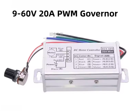
Easy Wiring: Features clearly labeled screw terminals for power input (V+/V-) and motor output (M+/M-), with a dedicated 2-pin control header for optional remote potentiometer connection.
Technical Specifications
Pinout & Interface Guide
The controller features clearly labeled screw terminals for all power connections.
Power Terminals
-
V+ / VIN+ (Power Input +): Connect the positive terminal of your DC power source (9V-60V) here. Observe correct polarity.
-
V- / VIN- (Power Input -): Connect the negative terminal (ground) of your DC power source here.
Motor Terminals
-
M+ (Motor Output +): Connect to one wire of your brushed DC motor.
-
M- (Motor Output -): Connect to the other wire of your brushed DC motor.
-
Note: Motor wires are non-polarized. If the motor runs in the wrong direction, simply swap the two wires at the M+ and M- terminals.
Control Interface
-
Speed Control Knob: The dedicated rotary knob provides manual, stepless speed adjustment from 0% to 100% duty cycle.
-
Power Switch: The separate switch provides convenient on/off control without disturbing your speed setting.
-
Fault LED: Illuminates during fault conditions to alert you to issues.
Optional Remote Control Header (if equipped)
Usage Guide
Important Safety Warnings
-
DC ONLY: This controller is designed strictly for DC circuits. Never connect it to AC mains power (e.g., 110V or 220V AC). Doing so will instantly destroy the controller and poses a serious fire hazard.
-
Polarity Matters: Do not reverse the positive and negative terminals of the DC power supply. This will damage the controller.
-
Motor Type: This controller is for brushed DC motors only. It is NOT compatible with brushless DC motors (BLDC), stepper motors, or AC motors.
-
Current Limits: The controller is rated for 20A continuous. Prolonged operation at currents exceeding 20A may cause overheating. The 25A peak rating is for short-duration surges.
-
Proper Heat Sinking: For high-current applications, ensure adequate airflow around the controller. Do not mount in a sealed enclosure without ventilation.
Wiring Guide
Step-by-Step Operation
-
Mount the Controller: Secure the module in your enclosure using the mounting holes. Ensure adequate ventilation for high-power operation.
-
Connect the Motor: Connect your brushed DC motor to the M+ and M- terminals. Polarity is not critical for initial testing—if direction is wrong, swap the wires.
-
Connect the Power Supply: Connect your DC power source (9V-60V) to the V+ and V- terminals. Ensure the power switch is in the OFF position during wiring.
-
Set Initial Speed: Turn the speed control knob fully counter-clockwise to its minimum speed position.
-
Apply Power: Turn on your DC power source, then flip the controller’s power switch to the ON position.
-
Adjust Speed: Slowly turn the speed control knob clockwise. The motor will begin to spin and increase in speed as you turn. Adjust until you reach the desired speed.
-
Stop the Motor: Flip the power switch to the OFF position. Your speed setting is preserved for next use.
Q: What types of motors can I use with this controller?
This controller is designed for brushed DC motors only operating at 9V to 60V. It is ideal for motors found in power tools, pumps, fans, conveyors, and small electric vehicles. It is not compatible with brushless DC motors (BLDC), stepper motors, or AC motors.
Q: What is the real-world current and power limit?
The controller is rated for 20A continuous current and can handle peak currents up to 25A. The maximum power depends on your input voltage:
-
At 12V: Up to 240W (12V × 20A)
-
At 24V: Up to 480W (24V × 20A)
-
At 60V: Up to 1200W (60V × 20A)
For sustained operation, it is recommended to stay within the 20A continuous rating.
Q: Can I use this controller with a 24V or 48V battery system?
Yes. The controller accepts any DC voltage from 9V to 60V, making it compatible with 12V, 24V, 36V, and 48V systems. Always ensure your motor is rated for the voltage you apply.
Q: Can I control this with an Arduino or other microcontroller?
Yes, with modification. The controller accepts a 0-5V analog signal for remote speed control. You can use an Arduino’s PWM output with a low-pass filter to generate this analog signal, or you can use a digital potentiometer. The onboard speed control knob can be removed or bypassed to accept an external control signal
Q: What is the advantage of the separate power switch?
The independent power switch allows you to turn the motor on and off without disturbing your speed setting. This is particularly useful in applications where you need to maintain a specific speed setting across multiple power cycles.
Q: What power supply should I use?
Use a DC power source with a voltage between 9V and 60V that matches your motor’s rated voltage. The power source must be capable of delivering at least the current your motor will draw (up to 20A continuous). Examples include:
-
12V, 24V, 36V, 48V battery packs
-
12V-60V regulated power supplies
-
Industrial DC power systems
Q: What is the PWM frequency and why does it matter?
The controller operates at a 25kHz PWM frequency. This frequency is above the range of human hearing, which eliminates the annoying high-pitched whine often heard with lower-frequency controllers (e.g., 500Hz-1kHz). It also provides smoother motor operation with less torque ripple.
Q: The controller gets warm. Is this normal?
Some warmth is normal when switching currents near 20A. The controller is designed to dissipate heat through its components and PCB. However, if it becomes too hot to touch or the fault LED activates, you may be exceeding the recommended continuous current rating. Ensure adequate ventilation and check that your motor is not drawing excessive current due to mechanical binding or stalling
Q: What does the fault LED indicate?
The fault LED illuminates when one of the protection circuits is activated. Common causes include:
-
Overcurrent: Motor current exceeded the 20-25A safe range
-
Over-temperature: Controller temperature exceeded safe limits
-
Low voltage: Input voltage dropped below minimum operating threshold
If the fault LED activates, reduce the load, allow the controller to cool, or check your power supply voltage.
Q: The controller doesn't work. The motor doesn't move.
Follow this checklist:
-
Check Power Switch: Ensure the power switch is in the ON position.
-
Check Power: Verify with a multimeter that you have the correct DC voltage at the V+ and V- terminals (9V-60V).
-
Check Polarity: Ensure your power supply is connected with the correct polarity (+ to V+, – to V-). Reverse polarity can damage the controller.
-
Check Knob Position: Ensure the speed control knob is turned clockwise past the minimum speed position.
-
Check Fault LED: If the fault LED is illuminated, refer to the fault LED section above.
-
Test the Motor: Connect your motor directly to the power source (briefly) to ensure it works.
Q: The motor runs at full speed all the time, and the knob doesn't control it.
This indicates that the power MOSFET may have failed “shorted.” This can happen if the controller was overloaded beyond its capacity, experienced a short circuit, or had reverse polarity applied. You will likely need to replace the controller.
Q: The motor runs in the wrong direction.
This is easily fixed. Turn off the power, swap the two motor wires at the M+ and M- terminals, and then reapply power.
Q: The motor vibrates or runs roughly at low speeds.
This can sometimes happen with PWM controllers at very low duty cycles. Try the following:
-
Ensure your power supply is stable and well-regulated.
-
Check that the motor is in good condition (brushes, bearings).
-
Increase the speed slightly—some motors have a minimum speed below which they cannot run smoothly due to their design.
Q: Can I use this controller to dim LEDs?
While technically possible, this controller is optimized for inductive loads like motors. For LED dimming, a dedicated LED driver is recommended. If you choose to use this controller for LED applications, ensure the LED load does not exceed the voltage and current ratings.