Product Overview
The ESP-01 WiFi Module is a compact, powerful, and cost-effective solution for adding wireless connectivity to your projects. Based on the revolutionary ESP8266 chip from Espressif Systems , this module single-handedly transformed the IoT landscape by bringing full WiFi capabilities to microcontroller projects at an unprecedented price point .
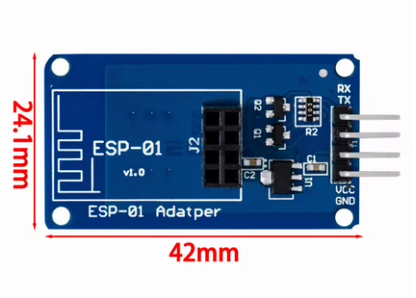
Despite its tiny footprint of just 14.3mm × 24.8mm , the ESP-01 packs a complete 32-bit microcontroller with an integrated TCP/IP stack, allowing it to function either as a standalone application processor or as a WiFi add-on for other microcontrollers like Arduino . It supports 802.11 b/g/n wireless standards and can operate in STA (station), AP (access point), or STA+AP modes , providing exceptional flexibility for IoT applications .
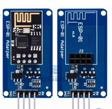
The module is designed with a DIP-8 package , featuring a 2×4 pin header that makes it easy to mount on breadboards or integrate into custom PCBs . Its unique plug-in design allows for flexible deployment, particularly suitable for automated, large-scale, and low-cost modern manufacturing processes . Whether you are building smart home devices, industrial wireless controls, or wearable electronics, the ESP-01 provides a proven, reliable, and well-supported platform for your IoT innovations.
Key Features
-
Integrated 32-bit Processor: Powered by the Tensilica L106 32-bit RISC processor, capable of running at up to 160MHz. It can function as a standalone microcontroller without the need for an external host .
-
Complete WiFi Solution: Supports 802.11 b/g/n protocols at 2.4GHz, with built-in TR switch, balun, LNA, power amplifier, and matching network—all integrated into the module .
-
Multiple Operating Modes: Supports Station (STA), Access Point (AP), and Station+AP (STA+AP) modes, allowing devices to connect to existing networks or create their own .
-
DIP-8 Package & Compact Size: Features a 2×4 pin header in a DIP-8 configuration, measuring just 14.3mm × 24.8mm, making it breadboard-friendly and easy to integrate .
-
Low Power Consumption: Supports various sleep modes with deep sleep standby current as low as 20µA and standby power consumption of less than 1.0mW (DTIM3) , ideal for battery-powered applications .
-
High-Performance Output: Delivers up to +19.5dBm output power in 802.11b mode with a receiver sensitivity of -90dBm , ensuring reliable wireless communication .
-
Rich Peripheral Interfaces: Provides UART, GPIO, I2C, I2S, PWM, and ADC interfaces for connecting sensors and actuators .
-
Easy Programming: Supports the Arduino IDE , MicroPython, and AT command set for quick development. Over-the-air (OTA) firmware updates are also supported .
-
Smart Configuration Support: Compatible with Smart Config and AirKiss one-click network configuration technologies, simplifying device onboarding .
-
Wide Operating Temperature: Rated for operation from -20°C to +85°C , suitable for industrial and outdoor applications .
Technical Specifications
Pinout & Interface Guide
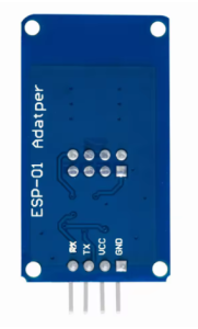
The ESP-01 module features a 2×4 pin header with the following pin assignments:
Important Wiring Notes
-
Power Supply: The ESP-01 requires a stable 3.3V DC power supply capable of providing at least 300mA during peak operation. Do not connect to 5V directly, as this will damage the module .
-
Boot Modes: The module’s boot mode is determined by the state of GPIO0 and GPIO2 :
-
Normal Operation: GPIO0 = HIGH, GPIO2 = HIGH
-
Programming Mode: GPIO0 = LOW, GPIO2 = HIGH (pull GPIO0 to GND during boot)
Usage Guide
Power Supply Requirements
The ESP-01 requires a 3.3V DC power supply with sufficient current capability. A 3.3V voltage regulator such as the AMS1117-3.3 or LM1117-3.3 is recommended for projects using higher voltage power sources .
Important: The ESP-01 is not 5V tolerant. Applying 5V to any pin can permanently damage the module. When connecting to a 5V Arduino, use a logic level converter for the TX/RX lines.
Programming & Development
There are several ways to program the ESP-01 module:
1. Using a USB-to-TTL Adapter
The most common method is to use a USB-to-TTL adapter (such as FTDI, CP2102, or CH340) to connect the module to a computer.
Wiring for Programming:
Enter Programming Mode:
-
Pull GPIO0 to GND (connect GPIO0 to GND)
-
Connect CH_PD/EN to VCC (pull HIGH)
-
Reset the module or cycle power
-
The module will now accept new firmware uploads
2. Using Arduino as a Programmer
An Arduino Uno can also be used to program the ESP-01, though a voltage level converter is strongly recommended to protect the ESP module .
3. Development Environments
-
Arduino IDE: Install ESP8266 board support via Boards Manager
-
MicroPython: Flash MicroPython firmware and develop using Python
-
PlatformIO: Professional development environment with ESP8266 support
-
AT Command Firmware: Pre-loaded firmware that allows control via simple serial commands
Example Project: Wi-Fi Controlled Relay
The ESP-01 is commonly used to create Wi-Fi controlled relays for smart home applications . The ESP-01 connects to a relay module, and when combined with firmware like Tasmota, provides a web interface for controlling AC or DC appliances .
Example AT Command Sequence
With the default AT firmware, the ESP-01 can be controlled via simple commands:
AT                    // Check communication
AT+CWMODE=1           // Set to Station mode
AT+CWJAP="SSID","PASSWORD"  // Connect to Wi-Fi
AT+CIPSTART="TCP","192.168.1.100",80  // Open TCP connection
AT+CIPSEND=5          // Send data
> HELLO                // Data to send
Q: What is the difference between ESP-01 and ESP-01S?
The ESP-01S is an “optimized” version of the ESP-01. Key differences include a simplified circuit with fewer pull-up resistors and often a different pin configuration for the Reset pin . The ESP-01S is generally considered more user-friendly for beginners. Both modules share the same core ESP8266 processor.
Q: How much flash memory does the ESP-01 have?
The original ESP-01 modules had 512KB of flash memory. However, most modern ESP-01 modules (typically with black PCBs) feature 1MB of flash storage, which is sufficient for most IoT applications . Some sellers may advertise “8MB RAM” which actually refers to 8Mbit = 1MB of flash.
Q: Can the ESP-01 run by itself or does it need a microcontroller?
The ESP-01 can function either way:
Q: How many GPIO pins does the ESP-01 have?
The ESP-01 exposes only 2 GPIO pins (GPIO0 and GPIO2) through the pin header . However, the ESP8266 chip itself has many more pins—they are simply not broken out on this compact module. For projects requiring more I/O, consider the ESP-12 series or development boards like NodeMCU.
Q: Does the ESP-01 support OTA (Over-the-Air) updates?
Yes. The 1MB version of the ESP-01 supports OTA firmware updates, allowing you to upload new code wirelessly without physically connecting to the module
Q: What voltage does the ESP-01 require?
The ESP-01 requires a stable 3.3V DC power supply. The operating voltage range is 3.0V to 3.6V . Do not connect 5V directly to the VCC pin.
Q: How much current does the ESP-01 need?
Average current consumption is about 80mA during normal operation, with peaks up to 300mA when transmitting . Your power supply should be capable of providing at least 300mA to ensure stable operation.
Q: Is the ESP-01 5V tolerant?
No. The ESP-01 is not 5V tolerant. Applying 5V to any pin (including RXD, TXD, or GPIO pins) can permanently damage the module. When interfacing with 5V devices like Arduino, use a logic level converter
Q: Why won't my ESP-01 boot/start?
Common boot issues include:
-
Insufficient power supply (current capability)
-
GPIO0 being pulled LOW (this enters programming mode)
-
Missing pull-up on CH_PD/EN (should be connected to VCC)
-
Unstable 3.3V supply
Q: The module gets hot. Is this normal?
The module will become warm during normal operation, especially when transmitting. However, if it becomes too hot to touch, there may be a short circuit or an overvoltage condition. Immediately disconnect power and check your wiring.
Q: How do I program the ESP-01?
To enter programming mode:
-
Connect GPIO0 to GND
-
Ensure CH_PD/EN is connected to VCC (3.3V)
-
Power on or reset the module
-
Upload firmware using a USB-to-TTL adapter
-
After upload, disconnect GPIO0 from GND and reset
Q: Why can't I upload code to my ESP-01?
Common upload issues:
-
GPIO0 not pulled LOW during power-on/reset
-
Incorrect serial connections (TX to RX, RX to TX)
-
Insufficient power supply (current sag during programming)
-
Wrong board selection in Arduino IDE (choose “Generic ESP8266 Module” or “ESP-01”)
-
Baud rate mismatch (try 115200 or 74880 for boot messages)
Q: What is the unusual baud rate 74880 used for?
When the ESP-01 first powers on, it outputs diagnostic information at 74,880 baud . This can be useful for debugging boot issues. After boot, the default AT command baud rate is typically 115200.
Q: Can I use MicroPython on the ESP-01?
Yes. MicroPython can be flashed to the ESP-01, though the limited flash memory (1MB) may restrict available libraries and features. Basic MicroPython functionality works well on this module.
Q: Why does my relay click briefly when powering on?
This is a known behavior of the ESP-01. During boot, GPIO0 is briefly pulled LOW, which can trigger connected relays if they are active-LOW . To avoid this, use a transistor buffer circuit or select a different GPIO pin if available.
Q: What can I build with the ESP-01?
Popular ESP-01 projects include:
-
Wi-Fi controlled relays and smart switches
-
Temperature/humidity monitors (with DHT11/DHT22)
-
Smart thermostats
-
Wireless sensors and data loggers
-
Home automation controllers
-
IoT data gateways
Q: Is the ESP-01 suitable for commercial products?
Yes, the ESP-01 is widely used in commercial IoT products due to its low cost, small size, and proven reliability. The DIP-8 package is particularly suitable for automated, large-scale manufacturing
Q: What firmware options are available?
Popular firmware choices include:
-
AT Command Firmware: Default firmware for co-processor mode
-
Tasmota: Open-source firmware for smart home devices
-
ESPEasy: User-friendly firmware for sensor applications
-
MicroPython: Python-based development
-
Arduino/C++: Custom code via Arduino IDE