Product Overview
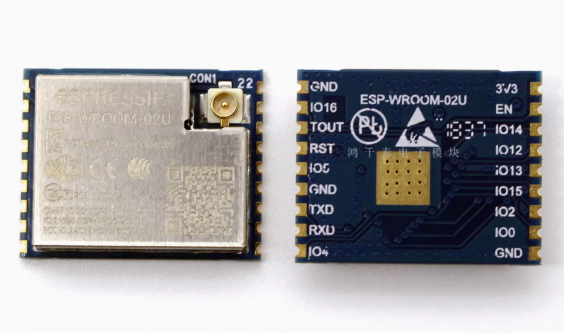
The ESP-WROOM-02U is a highly integrated, certified Wi-Fi module developed by Espressif Systems, the original creator of the ESP8266 ecosystem. This module represents the official, production-ready implementation of the ESP8266EX chip, featuring a compact form factor and a U.FL/IPEX connector that allows you to attach an external antenna for enhanced wireless range and flexibility .
What distinguishes the ESP-WROOM-02U from its counterparts (like the ESP-WROOM-02D) is its external antenna interface. While the 02D variant uses a PCB trace antenna, the 02U integrates a U.FL connector, enabling you to choose the optimal antenna for your specific application—whether that’s a high-gain antenna for long-range communication or a flexible antenna for tight enclosures .
At its heart lies the ESP8266EX chip—a Tensilica L106 32-bit RISC processor running at up to 160 MHz, with 2 MB (16 Mbit) of SPI flash memory and 50 kB of user-available SRAM . The module supports 802.11 b/g/n Wi-Fi protocols at 2.4 GHz, delivering up to +20.5 dBm output power and excellent receiver sensitivity down to -98 dBm .
Designed and manufactured by Espressif, the ESP-WROOM-02U comes preloaded with AT command firmware, allowing you to add Wi-Fi connectivity to any microcontroller using simple serial commands. It can also be reprogrammed as a standalone IoT processor using the Arduino IDE, MicroPython, or ESP-IDF.
Key Features
-
Official Espressif Module: Designed and manufactured by Espressif Systems, the creators of the ESP8266, ensuring the highest quality and reliable RF performance .
-
U.FL/IPEX Antenna Connector: Features an external antenna connector, allowing you to use a high-gain or custom antenna for extended range and flexibility in enclosure design .
-
2 MB Flash Memory: Equipped with 2 MB (16 Mbit) of SPI flash memory, providing sufficient storage for firmware, web interfaces, and OTA (Over-The-Air) firmware updates .
-
Integrated 32-bit Processor: Powered by the Tensilica L106 32-bit RISC processor running at up to 160 MHz, capable of running application code independently without an external microcontroller .
-
Complete Wi-Fi Solution: Supports 802.11 b/g/n protocols at 2.4 GHz with an external antenna interface. Delivers up to +20.5 dBm output power with receiver sensitivity down to -98 dBm .
-
Preloaded AT Command Firmware: Ships with industrial-grade AT firmware that allows control via simple serial commands, enabling rapid integration with any microcontroller.
-
Multiple Operating Modes: Supports Station (STA), SoftAP (Access Point), and SoftAP + STA modes, enabling devices to connect to existing networks or create their own .
-
Rich Peripheral Interfaces: Provides UART, HSPI, I2C, I2S, IR Remote Control, PWM, and 10-bit ADC interfaces, allowing connection to a wide variety of sensors, actuators, and display devices .
-
Ultra-Low Power Consumption: Features multiple sleep modes with deep sleep current as low as 20 µA, making it ideal for battery-powered applications .
-
Global Regulatory Certifications: Certified with FCC, CE-RED, TELEC, and RoHS, simplifying the certification process for commercial products .
-
Wide Operating Temperature: Rated for operation from -40°C to +85°C, suitable for demanding industrial environments and outdoor installations .
-
Compact SMD Package: Measures just 18.0 mm × 14.3 mm × 3.2 mm—the narrow form factor makes it ideal for space-constrained designs .
-
Upgradable Firmware: Supports local serial flashing and OTA (Over-The-Air) updates for flexible firmware management.
Technical Specifications
Pinout & Interface Guide
The ESP-WROOM-02U features 18 castellated pins for easy soldering to a host PCB .
Boot Mode Configuration
The module’s boot mode is determined by the state of GPIO0, GPIO2, and GPIO15:
Critical Notes:
-
GPIO15 must be pulled LOW during boot for both modes
-
GPIO2 must be pulled HIGH during boot (internal pull-up is present, but external pull-up is recommended)
-
GPIO0 must be LOW to enter programming mode, HIGH for normal operation
U.FL Antenna Connector
The module features a U.FL/IPEX connector for external antenna attachment. This allows you to:
-
Use a high-gain antenna for extended range
-
Place the antenna remotely from the module for optimal signal
-
Select an antenna that fits your enclosure design
Usage Guide
Power Supply Requirements
The ESP-WROOM-02U requires a stable 3.3 V DC power supply capable of providing at least 500 mA during peak operation . For reliable operation:
-
Use a low-dropout regulator (LDO) such as AMS1117-3.3 or LM1117-3.3
-
Add a 10 µF to 100 µF electrolytic capacitor and a 0.1 µF ceramic capacitor close to the VCC pin for power decoupling
-
Do not apply 5 V to any pin—this will permanently damage the module
Antenna Selection
Since the ESP-WROOM-02U uses a U.FL connector, you must attach an external 2.4 GHz antenna. Common options include:
-
Rubber duck antenna (2-3 dBi): General-purpose, good for most applications
-
High-gain antenna (5-8 dBi): For extended range
-
Flexible PCB antenna: For compact enclosures
-
Pigtail with external antenna: For remote antenna placement
Programming the ESP-WROOM-02U
Method 1: Using a USB-to-TTL Adapter
This is the simplest method for programming the module :
Enter Programming Mode :
-
Connect GPIO0 (pin 8) to GND
-
Connect GPIO15 (pin 6) to GND
-
Connect GPIO2 (pin 7) to VCC (pull HIGH)
-
Connect EN (pin 2) to VCC (pull HIGH)
-
Apply power or pulse RST LOW (pin 18)
-
Upload firmware via Arduino IDE or esptool
-
After upload, disconnect GPIO0 from GND and reset
Setting Up Arduino IDE
-
Install ESP8266 Board Package:
-
Open Arduino IDE → File → Preferences
-
Add to “Additional Boards Manager URLs”: https://arduino.esp8266.com/stable/package_esp8266com_index.json
-
Tools → Board → Boards Manager → Search “esp8266” → Install
-
Select Board:
-
Configure Flash Settings:
Using WiFiEspAT Library
For easy integration with Arduino, the WiFiEspAT library allows you to control the module using Arduino-style Wi-Fi commands without dealing with low-level AT commands :
#include <WiFiEspAT.h>
#define RX_PIN 16
#define TX_PIN 17
#define AT_BAUD_RATE 115200
const char* ssid = "your_SSID";
const char* password = "your_PASSWORD";
void setup() {
Serial.begin(115200);
Serial1.setRX(RX_PIN);
Serial1.setTX(TX_PIN);
Serial1.begin(AT_BAUD_RATE);
WiFi.init(Serial1);
WiFi.begin(ssid, password);
while (WiFi.status() != WL_CONNECTED) {
delay(1000);
}
Serial.println("Connected to Wi-Fi");
Serial.print("IP: ");
Serial.println(WiFi.localIP());
}
void loop() {
}
AT Command Example
With the default AT firmware, the ESP-WROOM-02U can be controlled via simple serial commands at 115200 baud. Important: AT commands require both Newline and Carriage Return (CR+NL) to be enabled in your serial terminal.
AT                    // Check communication
AT+GMR                // Check firmware version
AT+CWMODE=1           // Set to Station mode
AT+CWJAP="SSID","PASSWORD"  // Connect to Wi-Fi
AT+CIFSR              // Get IP address
AT+CIPSTART="TCP","192.168.1.100",8080  // Open TCP connection
AT+CIPSEND=5          // Send data
> HELLO                // Data to send
Updating AT Firmware
If your module has an older firmware version, you can update it over Wi-Fi using the AT+CIUPDATE command :
// Check current version
AT+GMR

// Connect to Wi-Fi
AT+CWMODE=1
AT+CWJAP="SSID","PASSWORD"

// Start firmware update (takes several minutes)
AT+CIUPDATE

// Module will automatically restart after update

// Verify update
AT+GMR
PCB Design Considerations
When integrating the ESP-WROOM-02U into a custom PCB :
-
Ensure the U.FL connector is accessible for antenna attachment
-
Keep the antenna area free from ground planes and metal obstructions
-
Use appropriate RF layout techniques for the antenna trace if using a PCB antenna
-
Follow Espressif’s PCB design guidelines for optimal RF performance
Q: What is the difference between ESP-WROOM-02U and ESP-WROOM-02D?
The primary difference is the antenna configuration :
-
ESP-WROOM-02U: Uses a U.FL/IPEX connector for an external antenna. Ideal when you need extended range or the module will be mounted inside a metal enclosure.
-
ESP-WROOM-02D: Uses an onboard PCB trace antenna. Suitable for compact designs where space is limited and range requirements are moderate.
Q: What is the advantage of the U.FL connector?
The U.FL connector allows you to:
-
Use a high-gain antenna for extended range (up to 100-200 meters in open space)
-
Place the antenna remotely from the module for optimal signal
-
Select an antenna that fits your enclosure (flexible, stubby, external)
-
Achieve better performance when the module is mounted inside a metal enclosure
Q: Can the ESP-WROOM-02U operate as a standalone microcontroller?
Yes. The ESP8266EX chip includes a 32-bit processor capable of running application code directly. You can program it with Arduino, MicroPython, or the ESP8266 SDK without requiring an external microcontroller
Q: How much flash memory does this version have?
The module is equipped with 2 MB (16 Mbit) of SPI flash memory . This is sufficient for most IoT applications, web interfaces, and OTA updates.
Q: Does the ESP-WROOM-02U support Bluetooth?
No. The ESP8266 series is Wi-Fi only. For Bluetooth capability, consider the ESP32 series modules like ESP32-WROOM-32.
Q: Is this module still recommended for new designs?
Important: Espressif has designated the ESP-WROOM-02U as “Not Recommended for New Designs” (NRND) . For new projects, consider the successor models like ESP8684-WROOM-02UC which offer improved performance and Bluetooth capability. However, the ESP-WROOM-02U remains an excellent choice for existing designs and applications where the ESP8266 ecosystem is already established.
Q: What voltage does the ESP-WROOM-02U require?
The module requires a stable 3.3 V DC power supply with an operating range of 2.7 V to 3.6 V . Never apply 5 V to the VCC pin or any GPIO pin—this will permanently damage the module.
Q: How much current does the ESP-WROOM-02U draw?
Current consumption varies by operating mode:
-
Normal operation (idle): 80 mA average
-
Wi-Fi transmitting: 120 mA – 170 mA
-
Wi-Fi receiving: 50 mA – 56 mA
-
Deep sleep: 20 µA
Q: Can I power the ESP-WROOM-02U with batteries?
Yes. The module’s low deep sleep current (20 µA) makes it suitable for battery-powered applications. A single 18650 lithium-ion cell (3.7 V) can be used with a 3.3 V LDO regulator. With proper deep sleep management, battery life of months is achievable.
Q: Why does my ESP-WROOM-02U not boot?
Common boot issues include :
-
GPIO15 not pulled LOW during boot
-
GPIO0 pulled LOW (this enters programming mode)
-
GPIO2 not pulled HIGH during boot (internal pull-up may be insufficient)
-
EN/CH_PD not connected to VCC
-
Insufficient power supply (current sag during startup)
Q: How do I put the ESP-WROOM-02U into programming mode?
To enter programming (UART download) mode :
-
Pull GPIO0 LOW (connect to GND)
-
Pull GPIO15 LOW (connect to GND)
-
Pull GPIO2 HIGH (connect to VCC)
-
Pull EN HIGH (connect to VCC)
-
Apply power or pulse RST LOW
Q: Why can't I upload code to my ESP-WROOM-02U?
Common upload issues:
-
GPIO0 not held LOW during power-on/reset
-
Incorrect serial connections (TX to RX, RX to TX)
-
Insufficient power supply (USB-to-TTL adapters may not provide enough current)
-
Wrong board selection in Arduino IDE (select “Generic ESP8266 Module”)
-
Missing pull-down on GPIO15
Q: What is the default baud rate for AT commands?
The default baud rate is 115200 bps. The bootloader outputs diagnostic information at 74880 baud during startup.
Q: How do I update the AT firmware?
You can update the AT firmware over Wi-Fi using the AT+CIUPDATE command :
-
Connect to a Wi-Fi network with AT+CWJAP
-
Send AT+CIUPDATE
-
Wait several minutes for the update to complete
-
The module will restart automatically
Q: Can I use the ESP-WROOM-02U with Arduino IDE?
Yes. Install the ESP8266 board package via Boards Manager, then select “Generic ESP8266 Module” as the board. Configure the flash size (2 MB) and upload speed appropriately.
Q: What antenna should I use with the U.FL connector?
Use any 2.4 GHz antenna with a U.FL/IPEX connector. Common options:
-
Rubber duck antenna (2-3 dBi): Good general-purpose range
-
High-gain antenna (5-8 dBi): Extended range (larger physical size)
-
Flexible PCB antenna: Compact, can be placed inside enclosures
-
Cable pigtail with external antenna: For remote antenna placement
Q: What can I build with the ESP-WROOM-02U?
Popular applications include:
-
Industrial IoT: Remote sensors with external antennas for metal enclosures
-
Smart home devices: Lighting control, smart plugs, thermostats
-
Environmental monitoring: Outdoor weather stations with external antennas
-
Medical devices: Patient monitoring, medical data transmission
-
Automotive: Remote diagnostics, vehicle communication
-
Sensor networks: Wireless sensor networks with extended range requirements
Q: Is the ESP-WROOM-02U suitable for commercial products?
Yes. The ESP-WROOM-02U is certified with FCC, CE-RED, TELEC, and RoHS . This makes it ideal for commercial products requiring regulatory approval, significantly reducing certification costs and time.
Q: What firmware options are available?
Popular firmware choices include:
-
AT Command Firmware: Default firmware for co-processor mode
-
NodeMCU (Lua): Open-source Lua-based firmware for easy programming
-
MicroPython: Python-based development for rapid prototyping
-
Arduino/C++: Custom code via Arduino IDE
-
ESP-IDF: Official Espressif development framework
Q: Does the ESP-WROOM-02U support OTA (Over-The-Air) updates?
Yes. The 2 MB flash memory supports OTA firmware updates, allowing you to upload new code wirelessly without physical connection to the module.
If you have further questions or require bulk pricing for business, educational, or industrial orders, please contact our support team. We’re here to help you build reliable, high-performance IoT solutions with the ESP-WROOM-02U WiFi module.