Product Overview
The 110V Single-Channel Wireless Receiver Board is a ready-to-use wireless control solution designed for direct integration into standard North American voltage circuits. This module serves as a bridge between a wireless remote and a high-power device, allowing you to control lighting, fans, pumps, or other 110V AC equipment without complex wiring or programming.
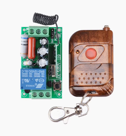
The system includes a compact receiver board capable of handling 110V AC power, paired with a stylish walnut-finished remote controller. The 433MHz wireless frequency ensures stable signal penetration through walls and obstacles, providing reliable control for home automation, industrial equipment, and DIY projects. Whether you are retrofitting existing lighting systems or building automated machinery, this module offers a simple, effective solution.
Key Features
-
Direct 110V AC Power Supply: The receiver is designed to be powered directly from standard North American mains voltage (90V–250V AC), eliminating the need for an external DC power adapter .
-
High-Power Relay Output: Features a built-in relay capable of switching loads up to 10A at 110V AC, suitable for controlling lights, fans, pumps, motors, and other household or industrial appliances .
-
433MHz Wireless Technology: Operates on the 433MHz frequency band, which offers better penetration through walls and longer range compared to 2.4GHz alternatives, typically achieving 30–50 meters of effective control indoors .
-
Learning Mode for Code Pairing: The receiver supports “learning mode,” allowing you to pair multiple remote buttons or replace lost remotes without any specialized programming tools .
-
Multiple Control Modes: Supports three selectable working modes—Toggle (Self-Lock), Latched, and Momentary (Jog) —configurable via DIP switches or jumpers on the receiver board .
-
Stylish Walnut Remote Controller: The transmitter is housed in a sleek, natural walnut wood casing, providing a premium look and feel suitable for home decor.
-
Easy Installation: The receiver board features screw terminals for line-in, neutral, and load connections, making it simple to wire into existing electrical boxes .
-
Status Indicator: An onboard LED provides clear visual feedback for power status and relay activation .
Technical Specifications
Pinout & Interface Guide
The receiver board is clearly labeled for easy wiring:
Power Input Terminals
Load Output Terminals
Control Interface
-
Learning Button: Used to pair new remote controllers or clear existing codes .
-
Mode Selection (DIP Switch/Jumper): Configures the relay operation mode.
-
Status LED: Indicates power, relay state, and programming status .
Working Modes Explained
The receiver supports three distinct control modes, configurable via DIP switches or jumpers :
Note: The factory default setting is typically Momentary mode .
Usage Guide
Wiring Instructions
IMPORTANT: Always disconnect mains power before wiring.
-
Power Off: Ensure the mains power is turned off and the circuit breaker is switched off.
-
Connect Power: Connect the Live (L) and Neutral (N) wires from the 110V AC source to the corresponding terminals on the receiver board .
-
Connect Load: Connect the live wire of your device (lamp, fan, etc.) to the “LOAD” terminal. Connect the neutral wire of your device directly to the mains neutral .
-
Check Connections: Double-check all connections are secure before applying power.
-
Power On: Restore mains power. The status LED should illuminate, indicating the receiver is ready.
Pairing the Remote (Learning Mode)
The receiver can learn the code from the remote control through a simple process :
-
Enter Learning Mode: Press and hold the learning button on the receiver for about 3–5 seconds until the status LED starts blinking slowly.
-
Transmit Signal: Press the button on the walnut remote controller while the LED is blinking.
-
Confirmation: The LED will flash 2 times (and may beep) to confirm successful learning, then turn off or stop blinking.
Note: The receiver can typically store multiple remote codes, allowing for control from several transmitters .
Selecting Control Mode
Configure the working mode using the DIP switches or jumpers on the receiver board :
Clearing All Learned Codes
To reset the receiver and clear all previously paired remotes :
-
Press and hold the learning button for 6–10 seconds.
-
The LED will flash rapidly (approximately 10 times) and the relay may toggle.
-
Release the button. All codes are now cleared.
Q: What is the maximum load this relay can handle?
The internal relay is rated for 10A at 110V AC. For resistive loads like incandescent lights or heaters, this equates to up to 1100W. For inductive loads (motors, pumps), it is recommended to derate the load to 5A–8A to account for startup surges
Q: What is the effective range of the remote?
In open outdoor space, the range can reach up to 100 meters. Indoors, through walls and floors, the effective range is typically 30–50 meters, depending on building materials (concrete/metal reduce range)
Q: Is this system compatible with smart home assistants like Alexa or Google Home?
This is a standalone RF remote system and does not have built-in Wi-Fi or smart home integration. However, you can pair it with a universal RF bridge or smart hub that supports 433MHz to enable app or voice control.
Q: What are the three working modes for?
-
Toggle: Standard on/off control for lights and general appliances.
-
Latched: Useful when you want separate buttons for ON and OFF (requires a 2-button remote).
-
Momentary: Ideal for motors, garage doors, or devices that should only run while the button is pressed
Q: The remote stopped working after I changed the battery. What should I do?
Sometimes the battery removal can reset the remote’s code transmission. You need to re-pair the remote with the receiver by entering the learning mode again.
Q: Can I use multiple remotes to control the same receiver?
Yes. The receiver can learn codes from multiple different remotes (often up to 20), allowing multiple family members or workers to control the same device
Q: The receiver clicks but the lamp/device doesn't turn on. What's wrong?
This indicates the relay is activating but the load circuit is not complete. Check:
-
Ensure the device’s neutral wire is connected directly to the mains neutral.
-
Ensure the device’s live wire is connected to the receiver’s “LOAD” terminal.
-
Verify the device itself is functional.
Q: How do I set the receiver to "Momentary" (hold to operate) mode?
Adjust the DIP switches or jumpers on the receiver board according to the label. If unsure, refer to the specific documentation for your module. The factory default is often Momentary mode
Q: Can I install this receiver inside a standard electrical wall box?
Yes, the compact PCB is designed to fit inside most standard electrical junction boxes. Ensure proper insulation and clearance to avoid short circuits with the 110V terminals
Q: Does the receiver get hot?
The receiver may become slightly warm during normal operation, especially under high loads (approaching 10A). Ensure it is installed in a well-ventilated area away from flammable materials.
Q: Can I use this to control a 12V DC device?
While the receiver is designed for 110V AC, you can use it to switch a 12V DC circuit by using an external 12V power supply. Connect the AC power to the receiver as normal, and connect the 12V load to the “LOAD” and “N” terminals (ensuring the DC load is within the relay’s 10A rating)
Q: What should I do if the receiver is installed inside a metal enclosure?
Metal enclosures can significantly reduce wireless signal range. If possible, mount the receiver in a plastic enclosure, or ensure the antenna wire is routed outside the metal box for better reception