Product Overview
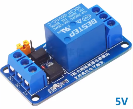
The BESTEP 1-Way Electromagnetic Relay Module is a high-performance, industrial-grade control module designed to provide a safe and reliable interface between low-voltage logic circuits and high-power devices. Featuring dual optocoupler isolation, this module creates a robust physical and electrical barrier between your sensitive microcontroller (such as Arduino, ESP32, or STM32) and the high-voltage load side, effectively eliminating electrical noise, protecting against back-EMF spikes, and ensuring system stability .
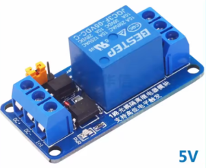
This versatile module supports both High-Level and Low-Level Trigger modes, selectable via an onboard jumper, making it compatible with virtually any digital logic system without the need for external level shifters . Whether you are controlling household appliances with a 5V Arduino or industrial equipment with a 3.3V ESP32, this module offers a flexible and reliable switching solution. The 5V version is optimized for standard 5V microcontroller systems and provides stable relay coil activation with a 5V supply.
With a relay contact rating of 10A at 250V AC or 10A at 30V DC, this module can handle a wide range of loads, from LED lighting and fans to motors, pumps, and industrial machinery . Its SPDT (Single Pole Double Throw) configuration provides both Normally Open (NO) and Normally Closed (NC) terminals, offering maximum wiring flexibility for your specific application .
Key Features
-
Dual Optocoupler Isolation: Features two optocouplers (typically PC817 or equivalent) providing enhanced electrical isolation between the control side and the high-voltage load side, ensuring superior noise immunity and protection against voltage spikes .
-
Universal Trigger Modes: Supports both High Level (Active HIGH) and Low Level (Active LOW) trigger modes, selectable via an onboard jumper, allowing compatibility with any microcontroller or logic system .
-
5V Coil Voltage: Designed for standard 5V microcontroller systems (Arduino, STM32, etc.), with the relay coil drawing approximately 70mA-80mA when activated .
-
High Power Switching: Relay contacts rated for 10A at 250V AC or 10A at 30V DC, suitable for controlling lights, fans, motors, solenoids, pumps, and industrial equipment .
-
SPDT Contact Configuration: Provides Common (COM), Normally Open (NO), and Normally Closed (NC) terminals for maximum wiring flexibility—use NO for OFF-by-default operation or NC for ON-by-default operation .
-
Clear Status Indicators: Onboard LED provides visual feedback: a power LED (green) illuminates when 5V power is applied, and a relay status LED (red) illuminates when the relay is activated .
-
Standard Interface: Equipped with screw terminals for the high-voltage side and a 3-pin header (VCC, GND, IN) for the control side, facilitating easy integration .
-
Built-in Flyback Diode: Includes a flyback diode across the relay coil to protect the driving circuit from inductive voltage spikes when the relay de-energizes .
-
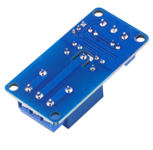
Compact and Durable: Small form factor with mounting holes for secure installation in control cabinets, enclosures, or on DIN rails .
Technical Specifications
Pinout & Interface Guide
Input Side (Control Interface)
Output Side (Load Terminals)
Jumper Settings
Status LEDs
Usage Guide
Wiring Instructions
IMPORTANT: Always disconnect mains power before wiring high-voltage loads.
Basic Connection (Control Side)
Load Connection (AC Example)
-
Connect the Live (L) wire from your AC source to the COM terminal
-
Connect the load (lamp, fan, motor) to the NO terminal for OFF-by-default operation
-
Connect the load’s Neutral (N) wire directly to the AC source neutral
Load Connection (DC Example)
-
Connect the positive (+) supply to the COM terminal
-
Connect the load’s positive wire to the NO terminal
-
Connect the load’s negative wire directly to the power supply ground
Setting the Trigger Mode
-
High Level Trigger (Active HIGH): Place the jumper on the “High” position. The relay activates when the IN pin is HIGH (3.3V–5V). This is the standard mode for most microcontrollers where you set the pin HIGH to turn the relay ON.
-
Low Level Trigger (Active LOW): Place the jumper on the “Low” position. The relay activates when the IN pin is LOW (0V). This is useful for fail-safe applications where the relay should remain OFF if the control signal is lost.
Example Arduino Code (High Level Trigger)
const int relayPin = 7;
void setup() {
pinMode(relayPin, OUTPUT);
digitalWrite(relayPin, LOW);
}
void loop() {
digitalWrite(relayPin, HIGH);
delay(5000);
digitalWrite(relayPin, LOW);
delay(5000);
}
Example Arduino Code (Low Level Trigger)
const int relayPin = 7;
void setup() {
pinMode(relayPin, OUTPUT);
digitalWrite(relayPin, HIGH);
}
void loop() {
digitalWrite(relayPin, LOW);
delay(5000);
digitalWrite(relayPin, HIGH);
delay(5000);
}
Example ESP32 / ESP8266 Code (High Level Trigger)
Since ESP32 operates at 3.3V logic, the HIGH signal (3.3V) is sufficient to activate the relay in High Level Trigger mode.
from machine import Pin
import time
relay = Pin(7, Pin.OUT)
relay.value(0)
while True:
relay.value(1)
time.sleep(5)
relay.value(0)
time.sleep(5)
Important Considerations
-
Power Supply: The module requires a stable 5V DC supply capable of providing at least 100mA . If you are powering it from an Arduino’s 5V pin, ensure the total current draw does not exceed the board’s capacity.
-
Dual Optocoupler Isolation: The dual optocouplers provide enhanced protection against electrical noise and voltage spikes, making this module ideal for industrial environments where motors and solenoids may generate back-EMF .
-
Inductive Loads: Although the module has a built-in flyback diode across the relay coil, for high-power inductive loads (motors, pumps), adding an external flyback diode across the load terminals is recommended to protect the relay contacts.
-
Default State: In Low Level Trigger mode, the relay remains OFF when the IN pin is HIGH or unconfigured, preventing unwanted activation during power-up .
Q: What is the difference between High-Level and Low-Level trigger?
High-Level trigger (Active HIGH) activates the relay when the control pin receives a positive voltage (3.3V–5V). Low-Level trigger (Active LOW) activates the relay when the control pin is connected to Ground (0V). The onboard jumper lets you select which mode fits your system .
Q: What is the advantage of dual optocoupler isolation?
Dual optocouplers provide enhanced electrical isolation between the control circuit and the high-voltage load. One optocoupler isolates the control signal, while the second isolates the relay coil drive circuit, offering superior protection against electrical noise, back-EMF spikes, and ground loops .
Q: Can I use this module with a 3.3V microcontroller like ESP32 or Raspberry Pi Pico?
Yes. The module accepts control signals from 3.3V to 5V. For High Level Trigger mode, a 3.3V HIGH signal is sufficient to activate the relay. For Low Level Trigger mode, a LOW signal (0V) works regardless of the logic voltage .
Q: What is the maximum load this relay can handle?
The relay contacts are rated for 10A at 250V AC or 10A at 30V DC . For inductive loads like motors or solenoids, it is recommended to derate to 5A–7A to account for startup surges.
Q: What happens if I set the jumper incorrectly?
If the jumper is set to High Trigger but your code sends a LOW signal, the relay will not activate (and vice versa). Simply adjust the jumper position to match your code’s logic or change your code to match the jumper setting .
Q: What power supply do I need for this module?
The module requires a stable 5V DC power supply capable of providing at least 100mA. The relay coil draws approximately 65-80mA when active, plus a small quiescent current .
Q: Does the module include a flyback diode?
Yes. The module includes a built-in flyback diode across the relay coil to protect the driving circuit from voltage spikes when the relay de-energizes . This protects your microcontroller from back-EMF.
Q: The relay clicks but my load doesn't turn on. What's wrong?
This indicates the relay is activating but the load circuit is incomplete. Check:
-
The load is correctly wired between COM and NO (or COM and NC)
-
The load’s neutral/ground is connected correctly
-
The load itself is functional
-
The load’s current does not exceed the relay’s 10A rating
Q: The relay clicks when I power on my controller. Why?
During power-up, microcontroller pins may briefly float or be in an undefined state. For Low Level Trigger mode, this should not activate the relay because the pin needs to be pulled LOW. Adding a 10kΩ pull-up resistor on the IN pin to VCC can ensure the relay remains OFF during startup if needed .
Q: Can I use this relay for 220V AC applications?
Yes. The contacts are rated for 250V AC, which is suitable for 220V/240V systems. Ensure proper insulation and clearance between the control and load sides for safety .
Q: The module's status LED lights up but the relay doesn't click. What's wrong?
The LED indicates the control signal is reaching the optocoupler. If the relay doesn’t click, check:
-
The VCC power supply is stable at 5V
-
The power supply can provide enough current (at least 100mA)
-
The jumper is set correctly for your trigger mode
-
The relay itself may be faulty (though rare)
Q: Can I use multiple relay modules with a single microcontroller?
Yes. Connect each module’s VCC and GND in parallel to the same 5V supply (ensure the supply can handle the total current), and connect each IN pin to a separate digital output pin on your microcontroller.
Q: Do I need external flyback protection for inductive loads?
The module already protects the control circuit with a built-in flyback diode across the relay coil. However, for high-power inductive loads (large motors, solenoids), adding an external flyback diode across the load terminals is still recommended to extend the relay’s contact life .
Q: What can I build with this 5V relay module?
Popular applications include:
-
Home automation: Lighting control, fan speed control, appliance switching
-
Industrial control: PLC output expansion, motor control, solenoid valves
-
IoT projects: Remote power switching with ESP8266/ESP32
-
Security systems: Alarm triggers, access control, gate openers
-
Automotive: 12V lighting, pump control (with external 12V supply)
Q: Can I use this to control a 12V DC motor or pump?
Yes. The relay contacts are rated for 10A at 30V DC, so it can safely switch 12V DC motors and pumps within the 10A limit. Ensure the motor’s stall current does not exceed the relay’s rating .
Q: Can I use this module without a microcontroller?
Yes. You can trigger the relay by manually connecting the IN pin to VCC (High Trigger mode) or GND (Low Trigger mode). This can be done with a simple push button or toggle switch .
Q: What is the expected lifespan of this relay?
The relay is rated for approximately 100,000 electrical operations at rated load . Actual lifespan depends on switching frequency and load type. For applications requiring very frequent switching, consider using a solid-state relay (SSR).