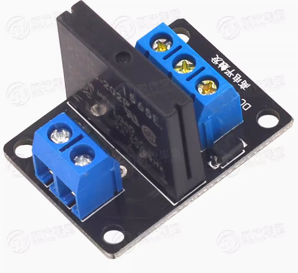
Product Overview
The 24V 1 Way Solid State Relay (SSR) is a high-performance, industrial-grade switching device designed to control AC loads using a standard 24V DC control signal. This module serves as a modern replacement for traditional electromagnetic relays, leveraging semiconductor technology (phototriac isolation) to switch high-voltage AC loads silently, without any moving parts, and with exceptional reliability .
This module is specifically engineered for DC control of AC loads. It accepts a 24V DC control signal from PLCs, microcontrollers (such as Arduino, ESP32), or other industrial control systems, and switches AC loads up to 240V at 2A (with some variants supporting higher currents). The module features zero-crossing switching technology, meaning it only turns on when the AC load voltage crosses zero volts. This minimizes electrical noise, reduces inrush current, and protects sensitive downstream equipment .
A key feature of this SSR module is its flexible trigger mode—it is available in both High Level Trigger (relay activates when control pin is HIGH) and Low Level Trigger (relay activates when control pin is LOW) versions. The low-level trigger version is often preferred for safety, as the relay remains off during power-up or if the control signal is lost .
Unlike mechanical relays, SSRs offer silent operation, faster switching speeds, no contact wear or arcing, and a significantly longer lifespan—often exceeding millions of switching cycles. They are ideal for controlling lighting, heating elements, fans, small motors, solenoids, and other AC-powered devices in industrial automation, HVAC systems, and IoT projects .
Key Features
-
Solid State Switching: Uses phototriac isolation with zero-crossing detection for silent, spark-free operation with no moving parts to wear out .
-
AC Load Control: Designed to switch AC loads up to 240V at 2A (resistive). Suitable for lights, fans, heaters, solenoids, and small motors .
-
24V DC Control: Accepts standard 24V DC logic signals from PLCs, Arduino, ESP32, and other industrial controllers .
-
Selectable Trigger Mode: Available in both High Level Trigger (active HIGH) and Low Level Trigger (active LOW) versions to match your application needs .
-
Optical Isolation: Provides galvanic isolation between the low-voltage control side and the high-voltage AC load side for enhanced safety and noise immunity. Isolation voltage typically rated at 2500-4000V AC .
-
Zero-Crossing Switching: Activates only when the AC voltage crosses zero, minimizing inrush current, reducing electromagnetic interference (EMI), and extending the life of connected devices .
-
Built-in Snubber Circuit: Includes an internal RC snubber to protect against voltage spikes and reduce EMI when switching inductive loads.
-
Status Indicator LED: Onboard LED provides clear visual confirmation of relay activation status.
-
Compact Module Design: Small footprint with screw terminals for easy wiring and DIN rail or panel mounting options .
Technical Specifications
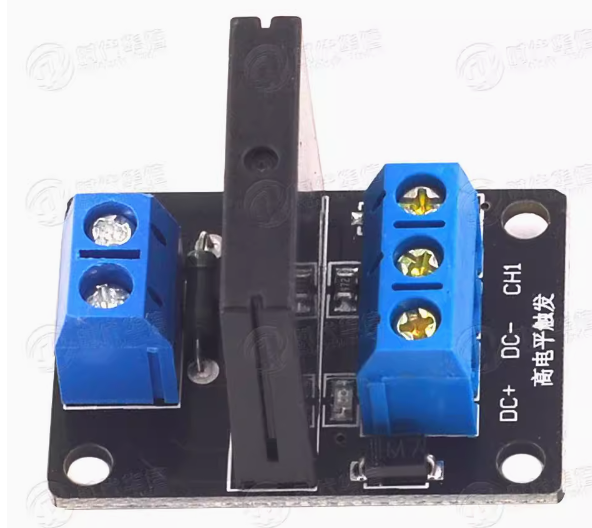
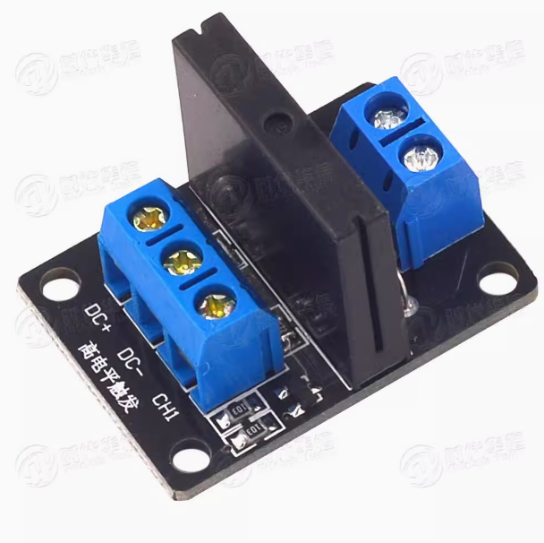
Pinout & Interface Guide
Input Side (Control Interface)
Trigger Mode Selection:
Output Side (Load Terminals)
Important Wiring Note
This SSR switches the live (hot) wire of the AC circuit . The AC neutral must be connected directly to the load’s neutral terminal. Do not connect the SSR output directly across the AC line without a load.
Usage Guide
Wiring Instructions
IMPORTANT: Always disconnect AC mains power before wiring high-voltage loads.
Basic Connection (Control Side)
AC Load Connection
-
Connect the Live (L) wire from your AC source to the AC IN terminal
-
Connect your AC load (lamp, fan, heater, motor) to the AC LOAD terminal
-
Connect the load’s Neutral (N) wire directly to the AC source neutral
Control Logic Examples
High Level Trigger Version:
Low Level Trigger Version:
Example Arduino Code (High Level Trigger)
const int relayPin = 7;
void setup() {
pinMode(relayPin, OUTPUT);
digitalWrite(relayPin, LOW);
}
void loop() {
digitalWrite(relayPin, HIGH);
delay(5000);
digitalWrite(relayPin, LOW);
delay(5000);
}
Example Arduino Code (Low Level Trigger)
const int relayPin = 7;
void setup() {
pinMode(relayPin, OUTPUT);
digitalWrite(relayPin, HIGH);
}
void loop() {
digitalWrite(relayPin, LOW);
delay(5000);
digitalWrite(relayPin, HIGH);
delay(5000);
}
Important Considerations
-
AC Load Only: This SSR is designed for AC loads only . Do not use it to switch DC loads, as the internal phototriac is designed to turn off when the AC current crosses zero.
-
Zero-Crossing Switching: The zero-crossing feature reduces electrical noise but introduces a slight delay (up to one half-cycle of AC, approximately 8.33ms at 60Hz) . This is normal and prevents inrush current spikes.
-
Minimum Load Current: Some SSRs require a minimum load current (typically 0.1A) to function properly. Very light loads may not trigger reliably .
-
Heat Dissipation: For continuous loads near 2A, ensure adequate airflow or use a heatsink to prevent thermal overload .
-
Testing Limitations: You cannot reliably test an SSR with a standard multimeter continuity test, as the multimeter’s test voltage is insufficient to trigger the phototriac.
Q: What is the difference between a Solid State Relay (SSR) and an electromagnetic relay (EMR)?
An SSR uses semiconductor components (phototriac) to switch loads with no moving parts, offering silent operation, faster switching, and longer lifespan. An EMR uses a mechanical coil and moving contacts, which can wear out over time and produce audible clicking
Q: Can I use this 24V AC SSR to switch DC loads?
No. This module is specifically designed for AC loads only . The internal phototriac is designed to turn off when the AC current crosses zero. For DC loads, use a DC-controlled DC SSR (MOSFET-based) or a mechanical relay.
Q: What is the maximum load this SSR can handle?
The module is rated for 2A at up to 240V AC for resistive loads . For inductive loads like motors, derate to 1A–1.5A to account for startup surges.
Q: What is zero-crossing switching?
Zero-crossing switching means the SSR only turns on when the AC voltage crosses zero volts. This minimizes electrical noise, reduces inrush current, and protects sensitive loads
Q: Can I use this SSR with a 5V microcontroller like Arduino?
Yes. The control signal threshold for High Level Trigger version is 3V–24V, making it compatible with 5V logic. For Low Level Trigger version, the LOW signal (0V) works regardless of logic voltage
Q: What power supply do I need for this module?
The module requires a stable 24V DC supply capable of providing at least 20mA. The typical control current is 7mA–15mA
Q: Why does my SSR not turn on when I test it with a multimeter?
A standard multimeter cannot generate enough voltage to trigger the phototriac inside the SSR. The SSR requires an actual AC load connected to function properly
Q: Does the SSR require a heatsink?
For 2A continuous load, a heatsink is typically not required due to the module’s low power dissipation (ON voltage drop ≤1.6V × 2A = 3.2W). However, ensure adequate airflow around the module
Q: The load stays on even when the control signal is OFF. What's wrong?
This can happen with very light loads (e.g., <0.1A) because the internal snubber circuit may pass a small leakage current (typically ≤5mA at 200VAC) . The SSR is designed for loads above this threshold.
Q: Can I use this SSR for 220V AC applications?
Yes. The module is rated for up to 264V AC, making it suitable for 220V/240V systems
Q: Why does my SSR have a delay when turning on/off?
The zero-crossing detection introduces a slight delay (up to one half-cycle of AC, approx. 8.33ms at 60Hz) to turn on. Turn-off delay is typically around 31ms max . This is normal and prevents electrical noise.
Q: Can I use multiple SSR modules with a single microcontroller?
Yes. Connect each module’s DC+ and DC- in parallel to the same 24V supply (ensure the supply can handle the total current), and connect each CH pin to a separate digital output pin.
Q: Do I need a flyback diode for inductive loads?
For motors and other inductive loads, adding an external snubber circuit (RC network) or varistor across the load terminals is recommended to suppress voltage spikes and extend SSR life
Q: What can I build with this 24V Solid State Relay?
Popular applications include:
-
Industrial Automation: PLC output control, motor switching, conveyor systems
-
HVAC Systems: Compressor and fan control
-
Home Automation: Lighting control, appliance switching with 24V control
-
IoT Projects: Remote AC load control with ESP32/ESP8266
-
Heating Systems: Temperature controller output switching
Q: Is this SSR suitable for controlling a motor?
Yes, with derating. For motor loads, it is recommended to operate at 50–70% of the rated current (1A–1.4A) to account for startup surges. The zero-crossing feature helps reduce inrush current
Q: Can I use this SSR for phase control (dimmable lighting)?
No. This SSR uses zero-crossing switching, which is designed for on/off control only. For phase control (dimmable lighting), you need an SSR without zero-crossing detection (random-turn-on type).
Q: How long does an SSR last compared to a mechanical relay?
SSRs have a significantly longer lifespan than mechanical relays due to the absence of moving contacts. They can handle millions of switching cycles, making them ideal for frequent switching applications