Product Overview
The 3V to 24V 1 Way Solid State Relay (AC Controlled DC) is a specialized semiconductor switching device designed to control DC loads using an AC control signal. Unlike conventional DC-input SSRs, this module accepts an AC voltage input (typically from a 24V AC transformer, thermostat, or HVAC controller) and switches a DC load on the output side .
This module is specifically engineered for applications where the control signal is AC, such as building automation systems, HVAC equipment, industrial controllers, and legacy systems that provide AC control outputs. The SSR features opto-isolated switching, providing complete electrical isolation between the AC control side and the DC load side for enhanced safety and noise immunity .
The module supports a wide AC control voltage range of 3V to 24V AC/DC (depending on the variant) and is available in both High Level Trigger and Low Level Trigger configurations . The output side is designed for DC loads, typically up to 3.5A at 24V DC or higher for some variants, making it suitable for controlling solenoids, valves, DC motors, LED lighting, and other DC-powered equipment.
Unlike mechanical relays, this SSR offers silent operation, faster switching speeds, no contact wear or arcing, and a significantly longer lifespan—ideal for applications requiring frequent switching or operation in hazardous environments where sparks must be avoided .
Key Features
-
AC Control Input: Designed to accept AC control voltages from 3V to 24V AC/DC, making it compatible with HVAC controllers, thermostats, and industrial AC output modules .
-
DC Load Switching: Output side switches DC loads up to 3.5A at 24V DC (or higher depending on variant), suitable for solenoids, valves, DC motors, and LED lighting .
-
Selectable Trigger Mode: Available in both High Level Trigger (active HIGH) and Low Level Trigger (active LOW) versions to match your application needs .
-
Optical Isolation: Provides galvanic isolation between the AC control side and the DC load side for enhanced safety and noise immunity. Isolation voltage typically rated at 2500V-4000V AC .
-
Fast Switching Speed: Solid-state design enables rapid switching with typical turn-on times of ≤ 10ms, suitable for high-frequency control applications .
-
Zero-Current Switching: Many AC-input models incorporate zero-crossing detection to minimize switching noise and inrush current .
-
Built-in Snubber Circuit: Includes an internal RC snubber to protect against voltage spikes and reduce EMI when switching inductive DC loads .
-
Status Indicator LED: Onboard LED provides clear visual confirmation of relay activation status .
-
Compact Module Design: Small footprint with screw terminals for easy wiring and DIN rail or panel mounting options .
Technical Specifications
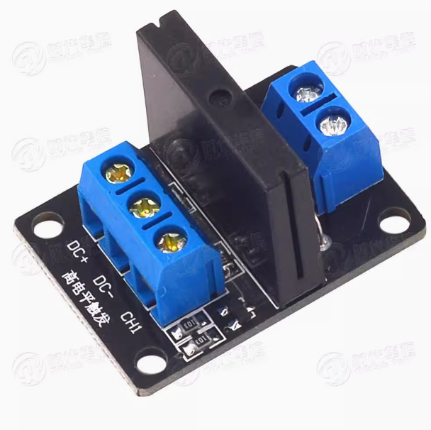
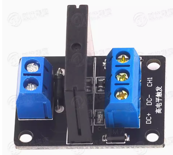
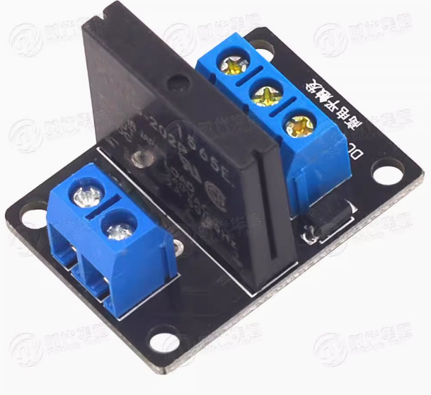
Pinout & Interface Guide
Input Side (AC Control Interface)
Output Side (DC Load Terminals)
Important Wiring Note
This SSR switches the negative (ground) side of the DC circuit for N-channel MOSFET outputs. The DC load’s positive wire should be connected directly to the positive terminal of the DC power supply. For P-channel or IGBT outputs, the polarity may differ—consult your specific module’s documentation .
Usage Guide
Wiring Instructions
IMPORTANT: Always disconnect power before wiring loads.
Basic Connection (AC Control Side)
DC Load Connection
-
Connect the positive (+) wire from your DC power supply to the load’s positive (+) terminal
-
Connect the load’s negative (-) wire to the SSR’s DC- terminal
-
Connect the SSR’s DC+ terminal to the negative terminal of your DC power supply
Control Logic Examples
High Level Trigger Version:
Low Level Trigger Version:
Example HVAC Control Application
This SSR is ideal for controlling a DC solenoid valve from a 24V AC thermostat output:
-
Connect the thermostat’s 24V AC output to the SSR’s AC+ terminal
-
Connect the thermostat’s common to the SSR’s AC- terminal
-
Connect the DC power supply to the load as described above
-
When the thermostat calls for operation, the SSR activates and powers the DC solenoid
Important Considerations
-
AC Control Signal: This SSR is designed for AC control inputs. If your control signal is DC, standard DC-input SSRs are available separately .
-
DC Load Only: The output side is designed for DC loads only. Do not use this module to switch AC loads .
-
Polarity: For MOSFET-based DC outputs, observe correct polarity to avoid damaging the internal body diode.
-
Flyback Diode: For inductive DC loads (solenoids, motors), add an external flyback diode across the load to protect the output transistor .
-
Heat Dissipation: For continuous loads near the maximum current rating, ensure adequate airflow or use a heatsink .
Q: What is the difference between an AC-controlled DC SSR and a DC-controlled AC SSR?
An AC-controlled DC SSR accepts an AC input signal (e.g., 24V AC from a thermostat) and switches a DC load. A DC-controlled AC SSR accepts a DC input (e.g., 5V from a microcontroller) and switches an AC load. Choose based on your control signal and load type .
Q: Can I use this SSR with a 24V AC thermostat output?
Yes. This module is specifically designed for such applications. It accepts AC control voltages from 3V to 24V AC/DC, making it directly compatible with standard HVAC thermostats and controllers .
Q: What is the maximum DC load this relay can handle?
The typical rating is 3.5A at 24V DC for standard models, but high-power variants can handle up to 40A. For inductive loads like motors, derate to 50–70% of the rated current to account for startup surges .
Q: Does this SSR require a separate power supply for the control side?
No. The control side is powered directly by the AC control signal. No additional power supply is needed for the input section .
Q: Can I use this SSR with a 3.3V or 5V DC control signal?
Yes. The module accepts both AC and DC control signals in the 3V–24V range. For DC control, connect the positive to AC+ and negative to AC- .
Q: What is the output voltage range for DC loads?
The output voltage range depends on the specific model but typically supports 5V to 48V DC. Some industrial models support up to 100V DC or higher .
Q: Does the SSR require a heatsink?
For loads above 2A, a heatsink is recommended to dissipate heat and ensure long-term reliability. Many modules include an integrated heatsink or provide mounting provisions .
Q: What is the typical on-resistance of the output?
The output on-resistance (RDS(on)) is typically ≤ 0.1Ω for MOSFET-based models, ensuring low power dissipation and high efficiency .
Q: Why does my SSR have a delay when turning on/off?
The turn-on delay (typically ≤10ms) is normal for AC-input SSRs due to the zero-crossing detection circuit that minimizes switching noise and inrush current .
Q: The SSR clicks but my load doesn't turn on. What's wrong?
This indicates the control circuit is functioning but the load circuit may be incomplete. Check:
-
The load’s polarity (for DC loads) is correct
-
The DC power supply is providing adequate voltage
-
The load’s current does not exceed the SSR’s rating
-
The load itself is functional
Q: Can I use this SSR to control a DC motor?
Yes, with derating. For motor loads, it is recommended to operate at 50–70% of the rated current to account for startup surges. Add a flyback diode across the motor terminals to protect the output transistor .
Q: Can I use multiple SSR modules with a single AC control source?
Yes. Connect multiple SSR inputs in parallel to the same AC control source, ensuring the source can provide sufficient current for all modules (typically <50mA total) .
Q: What is the expected lifespan of this SSR?
SSRs have an exceptionally long lifespan due to the absence of moving contacts. They can handle millions of switching cycles, making them ideal for applications requiring frequent operation .
Q: What can I build with this AC-Controlled DC Solid State Relay?
Popular applications include:
-
HVAC Systems: Control DC damper motors and solenoid valves from 24V AC thermostats
-
Building Automation: Interface legacy AC control systems with modern DC equipment
-
Industrial Control: Switch DC loads from AC output modules on PLCs
-
Process Control: Actuate DC valves and pumps from AC control signals
-
Energy Management: Retrofit AC-controlled systems to operate DC loads
Q: Is this SSR suitable for controlling a solenoid valve?
Yes. Solenoid valves are inductive loads; ensure the valve’s current rating is within the SSR’s capacity. Add a flyback diode across the valve terminals to protect the SSR output .
Q: Can I use this SSR for PWM (pulse-width modulation) control?
For standard AC-input models, the response time may be too slow for high-frequency PWM. Consult your module’s datasheet for maximum switching frequency specifications .
Q: What is the difference between zero-crossing and random-turn-on SSRs?
Zero-crossing SSRs turn on only when the AC input voltage crosses zero, minimizing switching noise. Random-turn-on (instant-on) SSRs respond immediately to the control signal, enabling phase control and faster response for inductive loads .