Product Overview
The 2-Way Relay Module is a versatile, high-performance control board designed to interface low-voltage logic circuits with high-power devices. Featuring optocoupler isolation and selectable high/low level trigger modes, this module provides a safe and flexible solution for controlling AC or DC loads from microcontrollers, PLCs, or other digital control systems.
This dual-channel module allows you to control two independent devices simultaneously. Available in 5V, 12V, and 24V versions, it matches a wide range of control system voltages. Each relay is rated for 10A at 250V AC or 10A at 30V DC, making it suitable for controlling lights, fans, motors, pumps, solenoids, and other household or industrial appliances .
The module features optocoupler isolation between the control side and the load side, providing excellent noise immunity and protection for your sensitive control electronics . The trigger mode can be set to either High Level or Low Level via onboard jumpers, allowing compatibility with virtually any logic system .
Key Features
-
Dual Independent Channels: Two separate relay channels allow independent control of two different loads from a single module .
-
Optocoupler Isolation: Provides electrical isolation between the control circuit and the high-voltage load, protecting your microcontroller from voltage spikes and electrical noise .
-
Selectable Trigger Mode: Each channel can be independently configured for High Level Trigger (active HIGH) or Low Level Trigger (active LOW) via onboard jumpers .
-
Multiple Voltage Options: Available in 5V, 12V, and 24V versions to match your control system voltage .
-
10A High Switching Capacity: Each relay contacts rated for 10A at 250V AC or 10A at 30V DC, suitable for controlling lights, fans, motors, pumps, and industrial equipment .
-
SPDT Contact Configuration: Each channel provides Common (COM), Normally Open (NO), and Normally Closed (NC) terminals for maximum wiring flexibility .
-
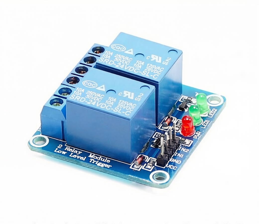
Status Indicator LEDs: Power indicator (green) and dual relay status indicators (red) provide clear visual feedback .
-
Fault-Tolerant Design: Even if the control line is disconnected or broken, the relay will not operate unintentionally, ensuring fail-safe behavior .
Technical Specifications
Pinout & Interface Guide
Input Side (Control Interface)
Output Side (Load Terminals) – Channel 1
Output Side (Load Terminals) – Channel 2
Jumper Settings (Trigger Mode Selection)
Status LEDs
Usage Guide
Wiring Instructions
IMPORTANT: Always disconnect mains power before wiring high-voltage loads.
Basic Connection (Control Side)
Setting the Trigger Mode
-
Low Level Trigger: Place the jumper on the LOW position. The relay activates when the IN pin is LOW (0V). This is ideal for fail-safe applications where the relay should remain OFF if the control signal is lost.
-
High Level Trigger: Place the jumper on the HIGH position. The relay activates when the IN pin is HIGH (VCC). This is the standard mode for most microcontrollers.
Load Connection (AC Example for One Channel)
-
Connect the Live (L) wire from your AC source to the COM terminal
-
Connect the load (lamp, fan, motor) to the NO terminal for OFF-by-default operation
-
Connect the load’s Neutral (N) wire directly to the AC source neutral
Load Connection (DC Example for One Channel)
-
Connect the positive (+) supply to the COM terminal
-
Connect the load’s positive wire to the NO terminal
-
Connect the load’s negative wire directly to the power supply ground
Example Arduino Code (Low Level Trigger)
const int relay1Pin = 7;
const int relay2Pin = 8;
void setup() {
pinMode(relay1Pin, OUTPUT);
pinMode(relay2Pin, OUTPUT);
digitalWrite(relay1Pin, HIGH);
digitalWrite(relay2Pin, HIGH);
}
void loop() {
digitalWrite(relay1Pin, LOW);
delay(3000);
digitalWrite(relay1Pin, HIGH);
delay(1000);
digitalWrite(relay2Pin, LOW);
delay(3000);
digitalWrite(relay2Pin, HIGH);
delay(1000);
digitalWrite(relay1Pin, LOW);
digitalWrite(relay2Pin, LOW);
delay(2000);
digitalWrite(relay1Pin, HIGH);
digitalWrite(relay2Pin, HIGH);
delay(2000);
}
Example Arduino Code (High Level Trigger)
const int relay1Pin = 7;
const int relay2Pin = 8;
void setup() {
pinMode(relay1Pin, OUTPUT);
pinMode(relay2Pin, OUTPUT);
digitalWrite(relay1Pin, LOW);
digitalWrite(relay2Pin, LOW);
}
void loop() {
digitalWrite(relay1Pin, HIGH);
delay(3000);
digitalWrite(relay1Pin, LOW);
delay(1000);
digitalWrite(relay2Pin, HIGH);
delay(3000);
digitalWrite(relay2Pin, LOW);
delay(1000);
digitalWrite(relay1Pin, HIGH);
digitalWrite(relay2Pin, HIGH);
delay(2000);
digitalWrite(relay1Pin, LOW);
digitalWrite(relay2Pin, LOW);
delay(2000);
}
Important Considerations
-
Power Supply: The module requires a stable power supply matching its voltage rating (5V, 12V, or 24V DC). The power supply must be capable of providing sufficient current (typically 100-200mA total) .
-
Optocoupler Isolation: The optocoupler provides electrical isolation between the control circuit and the high-voltage load. This protects your microcontroller from voltage spikes and electrical noise .
-
Inductive Loads: For motors, pumps, or solenoids, add a flyback diode across each load to protect the relay contacts from voltage spikes.
-
Default State: In Low Level Trigger mode, the relays stay OFF when the IN pins are HIGH or unconfigured, preventing unwanted activation during power-up .
-
Fault-Tolerant Design: Even if the control line is disconnected or broken, the relay will not operate, ensuring fail-safe behavior .
Q: What is the difference between Low Level Trigger and High Level Trigger?
Low Level Trigger means the relay activates when the IN pin is pulled LOW (0V). This is a safety feature—the relay remains off during power-up or if the control signal is lost. High Level Trigger means the relay activates when the IN pin is HIGH (VCC). The mode is selected via onboard jumpers
Q: What is the advantage of optocoupler isolation?
The optocoupler provides electrical isolation between the control circuit and the high-voltage load, protecting your microcontroller from voltage spikes, back-EMF, and electrical noise
Q: What is the maximum load each relay can handle?
Each relay contacts are rated for 10A at 250V AC or 10A at 30V DC . For inductive loads like motors, it is recommended to derate to 5A–7A to account for startup surges.
Q: Can I use different trigger modes for each channel?
Yes. Each channel has its own jumper (typically labeled S1 for Channel 1 and S2 for Channel 2), allowing independent configuration of trigger modes
Q: What is the difference between NO and NC terminals?
-
NO (Normally Open): The circuit is open when the relay is OFF. When the relay activates, it closes. Use NO for devices that should be OFF by default.
-
NC (Normally Closed): The circuit is closed when the relay is OFF. When the relay activates, it opens. Use NC for devices that should be ON by default
Q: What power supply do I need for this module?
Select the module version that matches your system voltage (5V, 12V, or 24V DC). The power supply must provide stable voltage and sufficient current (the module draws approximately 5mA quiescent plus 70-80mA per active relay for the 5V version)
Q: The relays click but my loads don't turn on. What's wrong?
This indicates the relays are activating but the load circuits are incomplete. Check:
-
Each load is correctly wired between COM and NO (or COM and NC)
-
Each load’s neutral/ground is connected correctly
-
The loads themselves are functional
-
The load currents do not exceed the relay’s 10A rating
Q: What is the expected lifespan of these relays?
Each relay is rated for approximately 100,000 electrical operations at rated load . Actual lifespan depends on switching frequency and load type.
Q: Can I use this relay module for 220V AC applications?
Yes. The contacts are rated for 250V AC, which is suitable for 220V/240V systems . Ensure proper insulation and clearance between the control and load sides for safety.
Q: The relay status LEDs light up but the relays don't click. What's wrong?
If the LEDs are on but the relays don’t click, check:
-
The VCC power supply is stable and matches the module’s voltage rating
-
The power supply can provide enough current
-
The jumper settings are correct for your trigger mode
-
The module may be faulty (rare)
Q: Do I need flyback diodes for inductive loads?
The module typically includes protection diodes across each relay coil. However, for high-power inductive loads (motors, solenoids), adding external flyback diodes across each load terminal is recommended to protect the relay contacts.
Q: Can I use multiple relay modules with a single microcontroller?
Yes. Connect each module’s DC+ and DC- in parallel to the same power supply (ensure the supply can handle the total current), and connect each IN pin to separate digital output pins on your microcontroller.
Q: What can I build with this 2-channel relay module?
Popular applications include:
-
Home automation: Control two lights, fans, or appliances independently
-
Arduino/ESP32 projects: Multi-device control for robotics and automation
-
Industrial control: PLC output expansion, motor control
-
Security systems: Alarm triggers, access control
-
Motor control: Control forward/reverse for a single DC motor using two relays
Q: Can I control a single motor's direction using two relays?
Yes. Using two relays, you can create an H-bridge configuration to control forward and reverse direction of a DC motor. Connect the motor between the COM terminals, and wire the NO and NC contacts appropriately.
Q: Can I use this module without a microcontroller?
Yes. You can trigger each relay by manually connecting the IN pin to VCC (High Trigger mode) or GND (Low Trigger mode). This can be done with simple push buttons or toggle switches.
Q: Is this module compatible with 3.3V microcontrollers like ESP32?
Yes, with consideration for the 5V version. For the 5V version, the High Level trigger threshold is typically 2.5V-5V, so a 3.3V signal is sufficient. For Low Level trigger, the 0V signal works regardless. For 12V and 24V versions, use external 12V/24V power for VCC and connect the control signal appropriately