Description
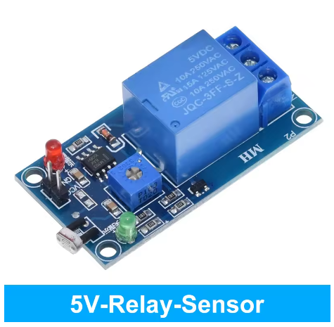
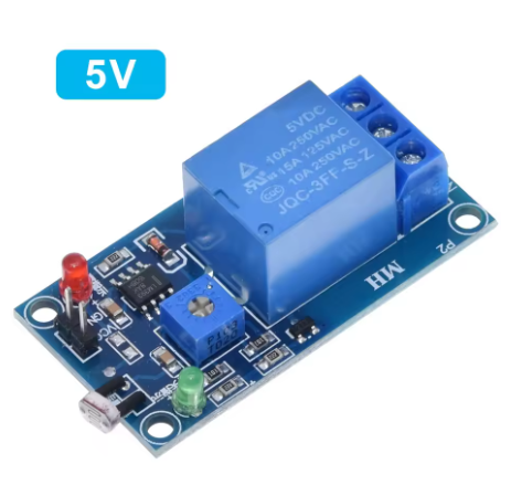
The 5V Relay Module with LDR is a complete, self-contained light-activated switching solution that combines a photoresistor (Light Dependent Resistor) with a powerful relay output on a single compact board. Unlike separate sensor and relay modules that require additional wiring and programming, this integrated module provides a simple “plug-and-play” system — when ambient light crosses the adjustable threshold, the relay automatically activates or deactivates, allowing you to directly control lights, fans, alarms, or any other high-power AC or DC equipment.
At the heart of the module is an LDR (photoresistor) that detects ambient light intensity. As light levels change, the resistance of the LDR changes proportionally. An onboard LM393 comparator processes this signal against a reference voltage set by the blue potentiometer, providing clean, stable switching without the jitter or noise associated with simple transistor-based circuits.
The module features an SPDT relay (Single Pole Double Throw) with screw terminals for COM (Common), NO (Normally Open), and NC (Normally Closed). The relay contacts are rated for 10A at 250V AC or 30V DC, making it capable of switching most common loads directly — from LED strip lights and household lamps to exhaust fans, pumps, and small motors.
Key features include a red power indicator LED, a blue relay status LED, an onboard potentiometer for precise sensitivity adjustment, and four mounting holes for secure installation. The module operates directly from a 5V DC power supply (USB charger, Arduino 5V pin, or dedicated 5V adapter) and requires no microcontroller or programming for basic operation — though it can easily be interfaced with one if more complex logic is needed.
This module is ideal for automatic night lights, garden lighting control, security lighting, darkroom equipment, automatic plant grow lights, daylight-responsive ventilation systems, and any application where light level triggers an action. It is suitable for both hobbyist projects and commercial installations such as signage lighting control and display case lighting.
Features
-
All-in-one design — LDR sensor and relay on a single PCB, no external components required
-
Adjustable light sensitivity via onboard blue potentiometer — set any brightness threshold
-
LM393 comparator for stable, jitter-free switching
-
SPDT relay contacts — COM, NO, NC terminals for flexible load wiring
-
High load capacity — 10A at 250V AC or 30V DC, suitable for most household and industrial loads
-
Dual LED indicators — Red LED for power, Blue LED for relay status
-
Standalone operation — works with just a 5V power supply, no microcontroller needed
-
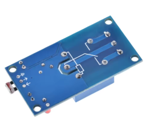
Four mounting holes (3mm) for secure panel or enclosure installation
-
Screw terminal blocks for reliable, tool-free wiring
-
Compact PCB design — fits easily into project boxes and control panels
Technical Parameters
Usage Guide
1. Module Overview
The board has three main sections:
-
LDR Sensor — The photoresistor (often with a clear or blue epoxy coating) detects ambient light. The LDR may be mounted directly on the board or on a short cable for remote positioning.
-
Comparator Section — Contains the LM393 IC and blue potentiometer for setting the light threshold.
-
Relay Section — Contains the 5V relay, screw terminals (COM, NO, NC), and status LEDs.
2. Wiring Instructions
3. Understanding Relay Operation
The relay acts as an electrically operated switch:
Typical configurations:
4. Sensitivity Adjustment
The blue potentiometer sets the light level threshold at which the relay changes state:
Adjustment tip: Cover the LDR completely with your hand. Slowly turn the potentiometer until the relay clicks (or the blue LED lights). This sets the “dark” threshold. Test by uncovering the LDR — the relay should change state when ambient light returns.
5. Standalone Operation (No Microcontroller Required)
The module works entirely on its own with just a 5V power supply:
-
Connect 5V and GND to a USB charger, 5V wall adapter, or battery pack
-
Connect your load (lamp, fan, alarm, etc.) to the relay terminals (COM and NO or NC)
-
Adjust sensitivity with the potentiometer
-
When ambient light crosses the threshold, the relay automatically switches
No programming — truly plug-and-play!
6. Using With a Microcontroller (Optional)
The module can also be used as a light sensor input for Arduino, ESP32, or other microcontrollers. Many versions provide a digital output (DO) pin that goes HIGH or LOW based on the light threshold.
Arduino Connection (if DO pin is present):
Sample Arduino Code:
int lightSensorPin = 7;
int ledPin = 13;
void setup() {
pinMode(lightSensorPin, INPUT);
pinMode(ledPin, OUTPUT);
Serial.begin(9600);
Serial.println("Light Sensor Ready");
}
void loop() {
int lightDetected = digitalRead(lightSensorPin);
if (lightDetected == HIGH) {
Serial.println("Dark detected - relay active");
digitalWrite(ledPin, HIGH);
} else {
Serial.println("Bright - relay inactive");
digitalWrite(ledPin, LOW);
}
delay(500);
}
Note: Output logic polarity varies by manufacturer. Test to confirm whether your module outputs HIGH or LOW when dark.
7. AC Load Wiring Example
To control a 110V/220V AC lamp (turns ON when dark):
AC Live (110V/220V) ──→ COM (Relay)
Lamp Live ──→ NO (Relay)
Lamp Neutral ──→ AC Neutral (direct)
Module VCC ──→ 5V DC Power Supply
Module GND ──→ 5V DC Power Supply GND
⚠️ Safety Warning: The module itself uses 5V DC, but the relay contacts can switch dangerous AC voltages. Always disconnect AC power before wiring, use proper insulation, and mount the module in an enclosure.
8. DC Load Wiring Example
To control a 12V DC LED strip (turns ON when dark):
12V Battery (+) ──→ COM (Relay)
LED Strip (+) ──→ NO (Relay)
LED Strip (-) ──→ Battery (-)
Module VCC ──→ 5V DC Power Supply
Module GND ──→ 5V DC Power Supply GND
9. Important Notes
-
Power supply: Use a regulated 5V power supply capable of providing at least 100mA. When the relay activates, current draw increases to approximately 50-70mA.
-
LDR placement: Position the LDR to measure the ambient light you want to detect — away from the load’s own light output to prevent feedback loops.
-
Response time: The module responds within milliseconds of the light threshold being crossed — fast enough for most applications.
-
LDR sensitivity range: The LDR responds to visible light (not infrared). It is ideal for daylight and artificial room lighting detection.
Q: What is the difference between this module and a separate LDR sensor + relay module?
This module is fully integrated — the LDR, comparator, and relay are all on one PCB. It requires only a 5V power supply to function as a complete light-activated switch. Separate modules require wiring between the sensor and relay, often need a microcontroller, and take up more space. This integrated design is simpler, more reliable, and ideal for standalone applications.
Q: Does this module need a microcontroller to work?
No. The module works in standalone mode with just a 5V power supply. When the light level crosses the adjustable threshold, the relay automatically switches. This makes it perfect for simple applications like automatic night lights, garden lighting, or darkroom equipment without any programming.
Q: How do I set the light threshold?
Adjust the blue potentiometer on the board:
-
Apply 5V power to the module
-
Expose the LDR to the light level at which you want the relay to switch
-
Slowly turn the potentiometer until the relay clicks (or the blue LED changes state)
-
Fine-tune by moving the LDR between dark and bright conditions
For a “lights ON at dusk” application, set the threshold at the desired evening light level.
Q: What loads can I control with this module?
The relay contacts are rated for 10A at 250V AC or 10A at 30V DC — sufficient for most common loads:
For inductive loads (motors, pumps, solenoids), we recommend derating to ≤5A or adding external snubber protection.
Q: Why is my module triggering randomly or too easily?
Possible causes:
-
Sensitivity too high — turn the potentiometer clockwise to reduce sensitivity
-
LDR exposed to changing light — position the LDR away from windows, passing car headlights, or the load’s own light output
-
LDR facing a light source directly — point the LDR toward the area you want to measure, not directly at a lamp
-
Power supply noise — use a regulated 5V power supply (not an unregulated “wall wart”)
-
Reflective surfaces — light bouncing off walls can cause inconsistent readings
Q: Why isn't my module switching at all?
Troubleshooting steps:
-
Check power — measure 5V across VCC and GND (the red power LED should be lit)
-
Check sensitivity — turn the potentiometer fully counter-clockwise (maximum sensitivity)
-
Cover the LDR completely — the relay should activate (blue LED lights)
-
Shine a bright light on the LDR — the relay should deactivate
-
Check load wiring — if the relay clicks but the load doesn’t work, verify your COM/NO/NC connections
Q: Can I use this module outdoors?
Yes, but with precautions:
-
The PCB is not weatherproof — mount inside a weatherproof enclosure (IP65 or higher)
-
The LDR can be placed behind a clear window (but note that glass may slightly reduce sensitivity)
-
For outdoor use, position the LDR to avoid direct sunlight saturation (early morning/late afternoon light is best for dusk/dawn switching)
-
Use weather-resistant cable glands for power and load wiring
Q: Can I use this with a 12V or 24V system?
This specific version is 5V only. For 12V or 24V systems, we offer dedicated versions of this module. Using a 5V module with a higher voltage power supply will permanently damage the board. Please check our product range for 12V and 24V LDR relay modules.
Q: What is the difference between NO and NC connections?
Choose based on whether you want the load to turn ON or OFF when the light threshold is crossed.
Q: How far can the LDR be from the module?
If the LDR is mounted on a cable (remote probe), the typical cable length is 10-12 inches (25-30cm). For longer distances, you can extend the wires up to approximately 3 meters (10 feet) using twisted-pair wire, but very long runs may pick up electrical noise and affect sensitivity. For best results, keep the LDR within 1 meter of the module.
Q: Can I use multiple LDR sensors with one module?
No. The module is designed for a single LDR input. For multiple light sensing points, you would need either multiple modules or a microcontroller reading multiple analog LDR sensors.
Q: What is the lifespan of the relay?
The relay is rated for approximately 100,000 switching cycles at rated load. In a typical night light application (switching twice per day), this translates to over 130 years of operation. For applications with frequent switching (e.g., every few minutes), the relay will wear out faster — consider our SSR (Solid State Relay) modules for high-frequency applications.
Q: Is this module suitable for professional/commercial use?
Yes. This module is used in:
-
Commercial lighting control — automatic signage lighting, display case lighting
-
Agricultural applications — greenhouse light-controlled ventilation, plant grow lights
-
Security systems — dusk-to-dawn security lighting
-
Industrial automation — light curtain detection, darkroom equipment
-
Building automation — daylight harvesting, automatic window covering control
For critical commercial installations, we recommend testing the module thoroughly under your specific lighting conditions before deployment.
Q: Can I use this module with a 3.3V microcontroller like ESP32?
The module’s VCC must be 5V (it will not operate reliably at 3.3V). However, you can still interface with a 3.3V microcontroller in two ways:
-
Use the relay output (isolated) — the relay contacts are completely separate from the control circuit, so no voltage compatibility issues
-
Use a voltage divider if your module has a DO (digital output) pin — use two resistors (e.g., 10kΩ and 20kΩ) to divide the 5V output down to 3.3V
Do NOT connect a 5V digital output directly to a 3.3V microcontroller pin.
Q: Does the LDR respond to all types of light?
The LDR (photoresistor) is most sensitive to visible light in the green-yellow spectrum (around 550nm). It responds to:
It has low sensitivity to red and infrared light. For infrared flame detection, please see our dedicated flame detection modules instead.
Q: How do I mount the module?
The PCB has four 3mm mounting holes at the corners. Recommendations:
-
Use M3 nylon screws and standoffs to prevent short circuits
-
Mount on a non-conductive surface (plastic, wood, or with insulating washers)
-
For metal enclosures, ensure the PCB does not contact the metal (use standoffs)
-
Position the LDR away from heat sources (the LDR is temperature-sensitive)
Q: Can I add a delay or timer function to this module?
The standard module has no built-in delay or timer — it switches immediately when the light threshold is crossed. If you need delay, hysteresis, or timer functions, you have two options:
-
Add external timer module (e.g., NE555-based delay timer) between the relay output and your load
-
Use a microcontroller (Arduino, ESP32) with the module’s DO output to implement custom timing logic
Q: What is the hysteresis of this module?
The LM393 comparator provides a small amount of hysteresis (typically a few percent) which prevents “chattering” when the light level is exactly at the threshold. This means the ON threshold and OFF threshold are slightly different, providing stable switching even in gradually changing light conditions (like dusk and dawn).