Product Overview
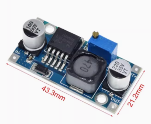
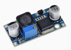
The LM2596 DC-DC Buck Converter Module is a high-performance, fixed-output step-down switching regulator designed to convert higher DC voltages (such as 24V) into a stable 3.3V output. Based on the industry-standard LM2596-3.3 chip from Texas Instruments, this module provides a simple, reliable, and efficient solution for powering 3.3V logic systems, microcontrollers, sensors, and other low-voltage devices from automotive batteries, industrial power rails, or higher voltage power supplies .
Unlike traditional linear voltage regulators that dissipate excess energy as heat, this switching regulator utilizes Pulse Width Modulation (PWM) technology to achieve conversion efficiencies of up to 92%. This means it runs much cooler and wastes significantly less power, making it ideal for battery-powered or enclosed applications. The module is capable of delivering up to 3A of continuous output current, enough to power multiple 3.3V devices simultaneously .
The fixed 3.3V output version eliminates the need for manual voltage adjustment—simply connect your input power and the module provides a precise, regulated 3.3V output. This makes it a perfect choice for applications where a stable, preset voltage is required without the risk of accidental misadjustment.
Key Features
-
Fixed 3.3V Output: Factory-preset to deliver a precise 3.3V output, eliminating the need for manual voltage adjustment and potential misconfiguration.
-
High-Efficiency Step-Down Conversion: Utilizes the LM2596 switching regulator to achieve up to 92% efficiency, minimizing power loss and heat generation compared to linear regulators .
-
Wide Input Voltage Range: Accepts DC input from 4.5V to 40V, making it compatible with 12V automotive, 24V industrial, and 36V solar panel systems .
-
3A High Output Current: Capable of delivering up to 3A of continuous output current. For loads above 2A, a heatsink is recommended to maintain optimal performance .
-
Fixed 150kHz Switching Frequency: Allows for smaller-sized filter components and lower output ripple compared to older regulator designs .
-
Comprehensive Protection: Includes built-in thermal shutdown and current-limit protection to safeguard the module and your connected devices under fault conditions .
-
Low Output Ripple: Delivers clean power with output ripple typically less than 30mV, suitable for sensitive electronics like microcontrollers and sensors .
-
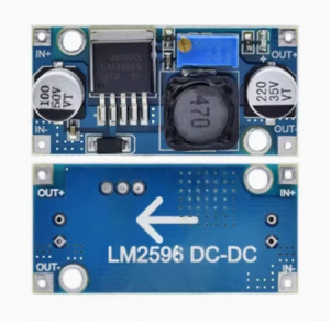
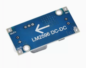
Simple 3-Terminal Interface: Clearly labeled input (IN+ / IN-) and output (OUT+ / OUT-) screw terminals for easy, tool-free wiring.
Technical Specifications
Pinout & Interface Guide
The module is clearly labeled for easy wiring. Connection points include:
Input Side (Power Source)
-
IN+ (VIN): Connect to the positive terminal of your DC power source (e.g., 12V battery, 24V power supply).
-
IN- (GND): Connect to the negative terminal (ground) of your DC power source.
Output Side (Load Connection)
-
OUT+ (VOUT): Connect to the positive terminal of your 3.3V device (e.g., ESP8266 3.3V pin, sensor VCC).
-
OUT- (GND): Connect to the negative terminal (ground) of your device.
Status Indicators
Usage Guide
Wiring Instructions
IMPORTANT: Always disconnect the input power source before wiring or modifying connections. Reverse polarity may damage the module as there is no built-in reverse protection .
-
Connect Input: Connect the positive wire of your DC power source (e.g., 24V battery) to the IN+ terminal. Connect the negative wire to the IN- terminal.
-
Connect Load: Connect the positive wire of your 3.3V device to the OUT+ terminal. Connect the negative wire to the OUT- terminal.
-
Power On: Apply power to the input. The power LED should illuminate, and your 3.3V device will be powered.
Example: Powering an ESP8266 from a 24V Source
This is a common and highly effective application for the LM2596-3.3 module. The ESP8266 (and other 3.3V microcontrollers) can be powered directly from a 24V industrial power supply or battery.
-
Connect the 24V power supply’s positive rail to IN+ and the negative rail to IN-.
-
Connect the ESP8266’s 3.3V pin to OUT+ and the ESP8266’s GND to OUT-.
-
The module will efficiently provide clean 3.3V power to your ESP8266, even in a noisy industrial environment, thanks to its built-in filtering capacitors and 150kHz switching frequency .
Example: Powering Multiple 3.3V Sensors from a 12V Battery
In a remote sensing application, you can power multiple 3.3V sensors (temperature, humidity, pressure) from a single 12V battery.
-
Connect the 12V battery’s positive terminal to IN+ and negative to IN-.
-
Connect the 3.3V sensors in parallel to the OUT+ and OUT- terminals (ensure total current does not exceed 3A).
-
The module will efficiently step down the 12V battery voltage to a stable 3.3V for all connected sensors.
Important Considerations
-
Step-Down Only: This is a buck (step-down) converter only. The output voltage (3.3V) must always be lower than the input voltage. The input must be at least 4.5V for proper regulation .
-
Heat Management: For loads above 2A, it is recommended to attach a small heatsink to the metal tab of the LM2596 IC to ensure long-term reliability and prevent thermal shutdown .
-
Fixed Output Advantage: Unlike adjustable versions, this module’s output is factory-set to 3.3V and cannot be accidentally changed, making it ideal for applications where a stable, preset voltage is critical .
-
Input Capacitor: For stable operation, especially when using long input wires, it is good practice to have a 100µF electrolytic capacitor near the input terminals .
Q: What is the difference between this fixed 3.3V module and the adjustable version?
The fixed 3.3V version has its output voltage internally set to 3.3V and has no potentiometer for adjustment. It is a “plug-and-play” solution for 3.3V applications. The adjustable version has a potentiometer that allows you to set the output to any voltage between 1.25V and 35V, offering greater flexibility but with the risk of accidental misadjustment
Q: Can this module increase voltage (boost)?
No. This is a buck (step-down) converter only. The output voltage (3.3V) must always be lower than the input voltage. To increase voltage, you would need a separate boost converter.
Q: What is the maximum output current I can draw from this module?
The module is rated for a maximum of 3A. For long-term reliability, it is recommended to stay within 2A – 2.5A, and a heatsink should be used for loads above 2A .
Q: Can I use this module to power an ESP8266 or other 3.3V microcontroller?
Yes. This module is excellent for powering 3.3V logic systems. The fixed 3.3V output is perfectly suited for ESP8266, ESP32 (3.3V version), STM32, and other 3.3V microcontrollers
Q: Can I use this module to power a 3.3V device from a 5V USB source?
Yes. The input voltage range is 4.5V to 40V, so a 5V USB source works perfectly. However, the output voltage (3.3V) is only 1.7V less than the input, which is acceptable.
Q: The module gets hot. Is this normal?
Some heat is normal, especially under high load. If it is too hot to touch, attach a heatsink to the LM2596 IC. Also, ensure the input voltage is not excessively higher than the output (e.g., 40V input to 3.3V output generates more heat than 12V to 3.3V)
Q: What is the input voltage range for this module?
The input voltage range is 4.5V to 40V DC. For a stable regulated 3.3V output, the input voltage must be at least 4.5V
Q: How accurate is the output voltage?
The LM2596-3.3 fixed output version has a guaranteed ±4% tolerance on output voltage under specified input voltage and output load conditions . This means the output will be between 3.17V and 3.43V.
Q: What is the efficiency of this converter?
The conversion efficiency can reach up to 92% under optimal conditions, significantly higher than linear regulators
Q: The module has power (LED is on) but there is no output voltage.
Follow this checklist:
-
Verify that your input voltage is above 4.5V.
-
Check that there is no short circuit on the output terminals.
-
Ensure your load is not drawing more than 3A, triggering the current limit protection.
Q: Can I connect the input in reverse?
No. Reversing the input polarity (connecting IN+ to negative and IN- to positive) may damage the module. This module does not have built-in reverse polarity protection . Always double-check your wiring before applying power.
Q: Can I use this module to charge a 3.3V battery?
While the module can provide 3.3V to charge a battery, it lacks a dedicated constant current (CC) charging profile. For unattended charging of lithium batteries, it is safer to use a dedicated battery charger module that provides proper CC/CV charging.
Q: What is the quiescent current when no load is connected?
The quiescent current is typically 5mA – 10mA when the module is powered but no load is connected .